


Wall corners are often singularities and have to be considered from an engineering point of view. Singularities are usually caused by reentrant corners and large stiffness jumps.
Since this is not a problem in the program, I can only explain one possible procedure for determining the design shear force using an example. As a basis for the example, I use the reference literature "Beispiele zur Bemessung nach DIN 1045-1; Band 1: Hochbau (3rd ed.)" by Ernst & Sohn. (You can find the abstract under Downloads.)
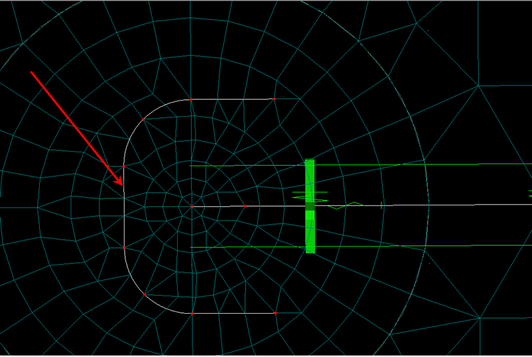
The aim is to determine the design shear force in the control perimeter. Determine the dimensions of the control perimeter according to DIN 1045-1, Figure 38 or Figure 39, and create these lines in RFEM (see Image 01).
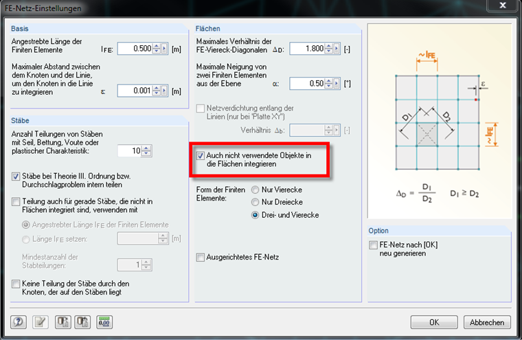
In order to include the created lines in the surface, please click on Calculation → FE Mesh Settings and then select the following option (see Image 02). If necessary, perform a mesh refinement.
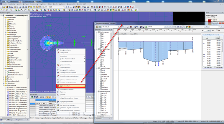
After calculating the governing load combination, select the three straight lines and then right-click one of them. Then, select the result diagrams (see Image 03).
Now, smooth the results of vmax,b with the following settings (see Image 04).
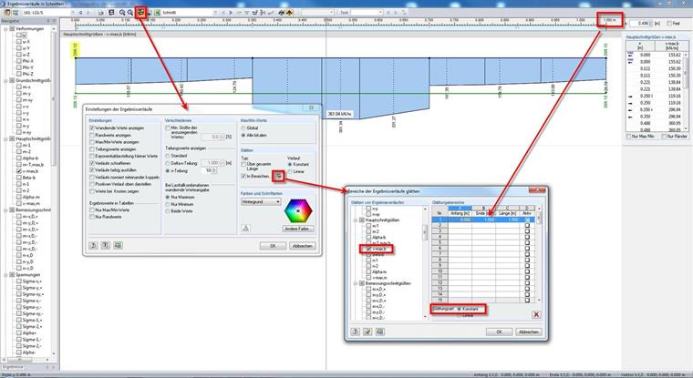
Note the smoothed value (209.12 kN/m in the image) and the total length (1.05 m in the image). Now, smooth the arc lines in similar ways as the straight lines. (You can only select lines of the same type at the same time to display the result diagrams.) Also, note the smoothed vmax,b (221.04 kN/m) and the length (0.889 m). Using these values, you can now determine the design shear force for the punching shear design:
vEd = β x (209.12 kN/m x 1.05 m + 221.04 x 0.889 m) / (1.05 m + 0.889 m) = 289.69 kN/m
with β = 1.35 for wall ends, and
β = 1.2 for wall corners (according to DIN 1045‑1; Figure 44)
VEd = 289.69 kN/m / β x (1.05 m + 0.889 m) = 416.08 kN