76 Results
View Results:
Sort by:
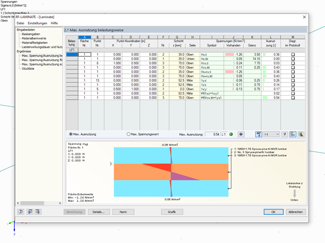
Question
How is coupling between individual layers controlled in the RF‑LAMINATE add-on module?
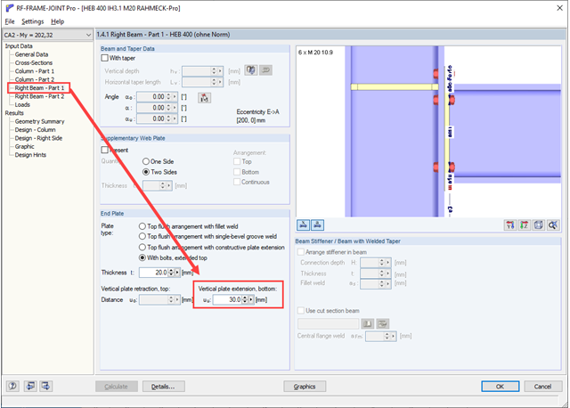
Question
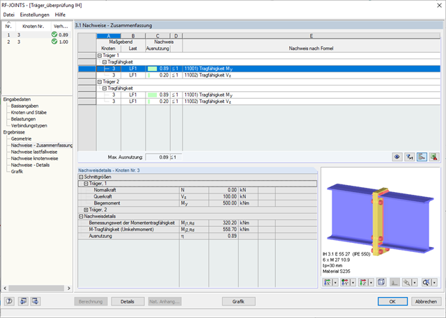
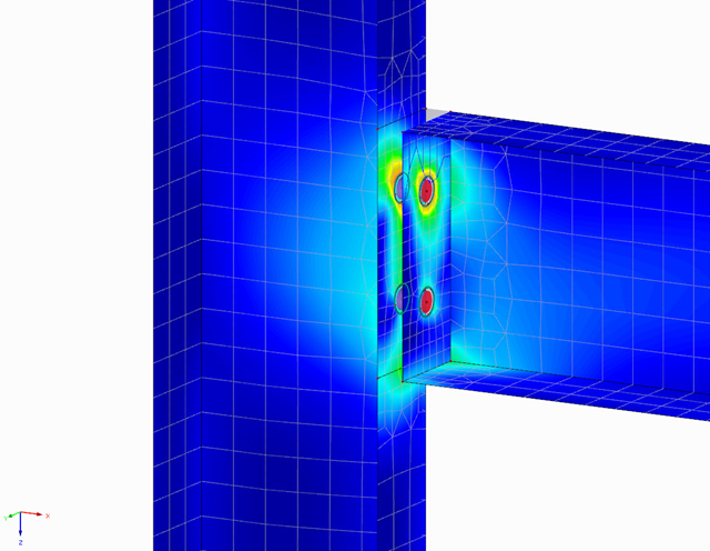
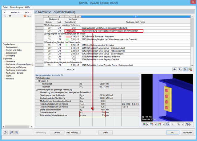
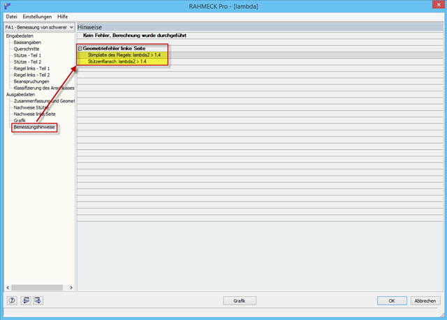
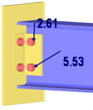
What does the design information mean:
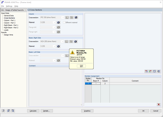
Geometry error left side:
End plate of the girder: Lambda2 >1.4
Column flange: Lambda2 >1.4
I cannot find an explanation in the manual or online.
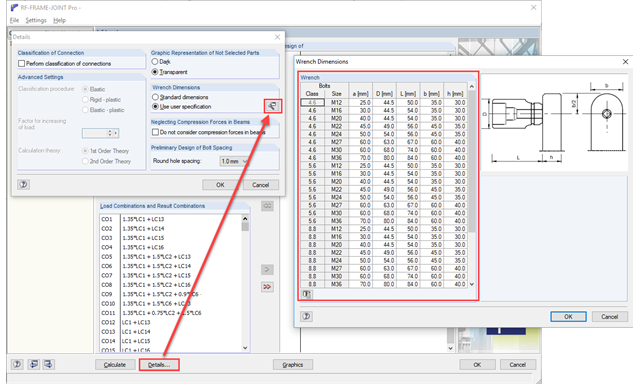
Question
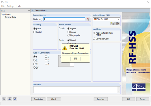
Why it is not possible to design a biaxial bending with the RF‑/JOINTS add-on module?
Question
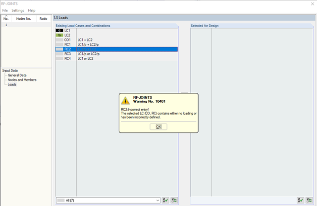
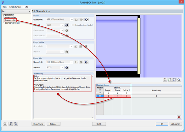
An attempt to design several connection nodes with the same geometry fails. According to the message, the connection geometry is different.
Question
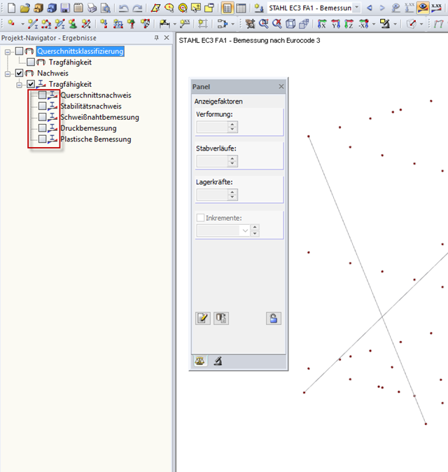
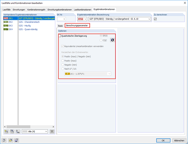
How do I superimpose generated equivalent loads from the seismic analysis?

Question
Why does the web service show "ERROR: Map not found."?
Question
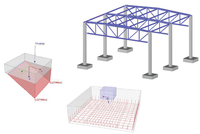
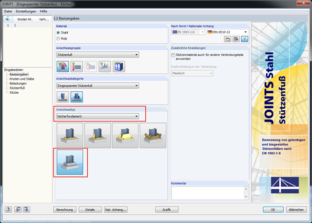
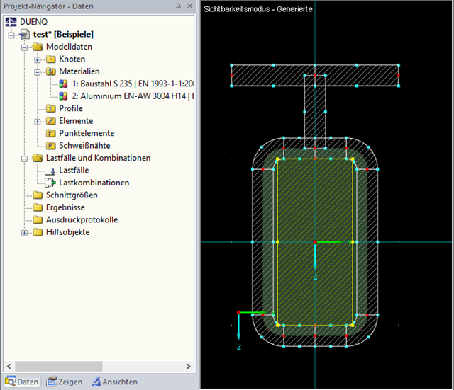
Do you have a program for designing columns restrained in concrete? It is not about the design of the bucket, but about the required embedment depth, the provided concrete stress, the check of the shear stress in the column, and so on.
Question
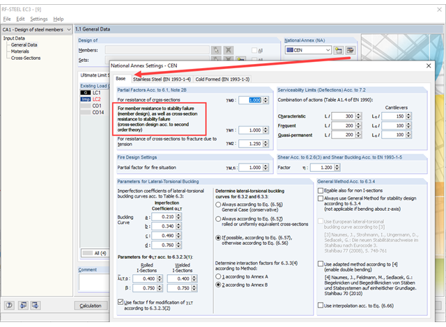
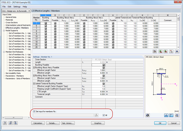
Is it possible to integrate several cross-sections into different materials when performing a flexural buckling analysis, or how can I apply several cross-sections to each other?
Question
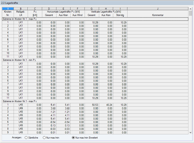
For a calculation, I activated the "Detailed Calculation" option. Have the support loads already been specified with the reduced dynamic coefficient for the design of the substructure?
Question
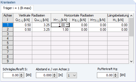
What is the meaning of the abbreviations for the crane loads in the CRANEWAY add-on module?