Considering Shrinkage in RF-CONCRETE Surfaces
Tips & Tricks
Concrete shrinks during hardening and drying. This results in a shrinkage deformation, which is described by the total shrinkage strain εcs. The total shrinkage strain is composed of the autogenous shrinkage εca (basic shrinkage strain) and the drying shrinkage εcd.
In the RF‑CONCRETE Surfaces add‑on module for RFEM 5, it is now possible to consider the shrinkage of the concrete directly in the module.
To do this, you have to activate the shrinkage in the settings for the serviceability limit state design. For the analytical method of the serviceability limit state design, you need the RF‑CONCRETE Deflect add‑on module; for the non-linear calculation, you need RF‑CONCRETE NL. If shrinkage is activated in the settings for the serviceability limit state design (in Window 1.1 General Data), the ‘Shrinkage’ tab becomes available in Window 1.3 Surfaces (see picture).
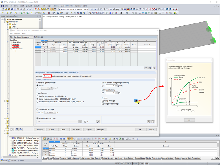
In this window, you can enter the parameters required to determine the shrinkage strain and make the following settings:
- considered concrete age
- type of cement
- concrete age at beginning of shrinkage
- relative air humidity
- alternative application of drying shrinkage and/or autogenous shrinkage
Furthermore, you can define a total shrinkage strain εcs determined elsewhere as user-defined shrinkage and select the surfaces to which this will be applied.
Alternative to the input in RF‑CONCRETE Surfaces, the shrinkage strain can also be entered in a separate load case as surface load (load type ‘Axial strain’), as was already possible in RFEM 4.
Keywords
Links
Write Comment...
Write Comment...
Contact us
Do you have questions or need advice?
Contact our free e-mail, chat, or forum support or find various suggested solutions and useful tips on our FAQ page.
Recommended Events
Videos
Models to Download
Knowledge Base Articles

New
Create and use the ADETS welded mesh in the RF-CONCRETE Surfaces add-on module of RFEM
Concrete on its own is characterized by its compressive strength. To have reinforced concrete, the participation of reinforcing steels contributes to it thanks to their resistance capacity both in compression and especially in traction.
Screenshots
Product Features Articles

Material Model Orthotropic Masonry 2D
The material model Orthotropic Masonry 2D is an elastoplastic model that additionally allows softening of the material, which can be different in the local x- and y-direction of a surface. The material model is suitable for (unreinforced) masonry walls with in-plane loads.
Frequently Asked Questions (FAQ)
- How do you define the descriptions of various reinforcement results,such as the required reinforcement?
- How are the creep and shrinkage for columns considered in RF‑CONCRETE Members?
- Why do I get such a small amount of reinforcement for the upstand beam? The amount of reinforcement for the downstand beams is significantly larger.
- How can I display the vertical deformation of a column in state II? I cannot find this setting for the serviceability limit state design.
- Is the preset crack width of, for example, wk = 0.3 mm also designed for primary cracks? According to the manual, the average strain is considered. Does this ensure that the primary crack does not exceed the value wk = 0.3 mm?
- How can I teach the program that it automatically increases the longitudinal reinforcement when calculating the deflection of the slabs so that the specified deflection is met?
- I calculate the deformations at time 0 and at time infinite. The deformations at the time infinite seem plausible to me. The deformations at time 0 seem significantly smaller and therefore implausible. What is the reason?
- For the design of a ring beam, I usually have Mz moments, which causes the formation of the compression and tension zone on the right and left of the cross-section. However, the reinforcement in CONCRETE is arranged at the top and bottom of the cross-section. How can I set the reinforcement to be arranged on the right and left?
- When calculating deformations in RF‑CONCRETE Members, I get jumps in the deformation diagram. Why?
- I get Error 108 when designing steel stress in RF‑CONCRETE Surfaces. Why?