The FF calculation can be activated in RFEM globally in the "General Data" of a model, "Options" tab. After selecting the corresponding option, a new load case or a calculation process called RF-FORM-FINDING is created in RFEM. An additional FF parameter is available for defining surface stress and prestress when entering cables and membranes. By activating the FF option, the program always starts the form-finding process before the pure structural calculation of internal forces, deformation, eigenvalues, etc., and generates a corresponding prestressed model for further analysis.

Input
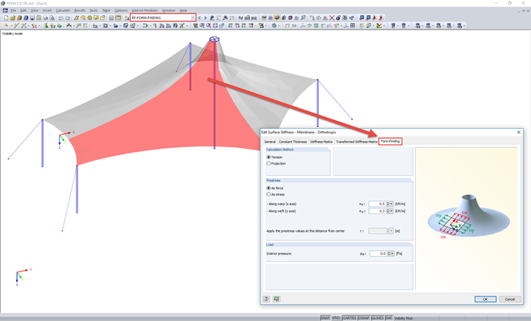
While defining a model of lightweight structures, you may realize the geometric position of the membranes and ropes is unclear. It is precisely the task of the FF process to find and fix this position in place. In the first instance, RFEM requires the initial input of the FF – elements. From the initial input, the program receives the information showing between which points a cable and which line polygon a membrane is included. Furthermore, the initial input requires a determination of surface stress value in the warp and weft directions of the membranes, including their application method (tension or projection), and the prestress level or sag dimension of the cable elements that should act according to the FF calculation. It should be noted that the initial shape of the FF elements is irrelevant.
When initially entering the FF elements in the program, you only need to ensure that all necessary connecting nodes and lines are integrated into the surfaces/members and that the meshing process can generate a mesh for all elements. If the meshing process fails, the operation is ended directly before the calculation.
Form-Finding
After a successful meshing, the program starts the FF process. This process adopts the mesh geometry and surface stress/prestress entered initially, and displaces the position of the mesh elements until the surface stress on the FE element is in equilibrium with the boundary conditions. The description of the surface stress on the membrane mesh elements can be defined in two ways.
The tension method describes a surface stress vector, which can move freely in space until it reaches the target position. In contrast, the projection method describes a surface stress vector that can move semi-freely in space while being fixed to its XY coordinates. It can happen that in the case of prestress vectors freely movable in space, the tangential vectors can contract to a point in the center, especially for rotationally symmetric models with conical shapes. You can counteract this reaction by fixating the surface stress vectors in the XY plane when using the projection method.
This shifting step is done iteratively using the URS method by Prof. Dr.-Ing. K.-U. Bletzinger and E. Ramm.
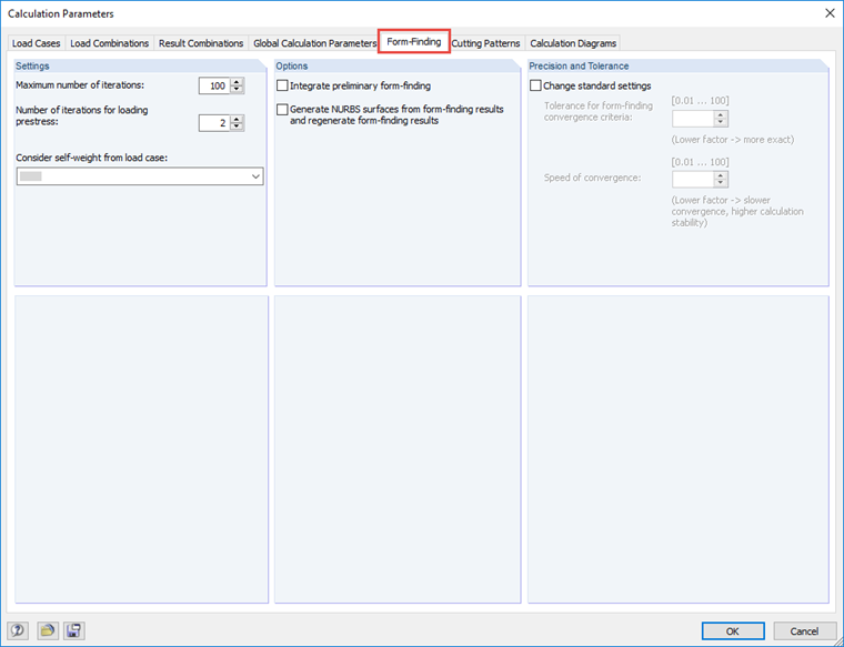
To control the iteration process, there is a separate "Form-Finding" tab in the Calculation Parameters dialog box. The following options are available:
Maximum Number of Iterations
In general, the FF calculation should end before reaching this limit due to compliance with all tolerance limits. If the tolerance limits are not met after the permitted number of iterations, the program displays a warning message with the option to continue using the intermediate result.
Number of Iterations for Loading Prestress
This number specifies in how many iterations the FF calculation should apply the prestress to the elements with the previously defined value. Once this limit has been exceeded, the program stops applying the initial value of the prestress again and again during the FF calculation. By increasing the value for an isotropic surface stress with the tension method or an isotropic/orthotropic surface stress with the projection method, the program converges to a stable solution. Due to the biaxial curvature, it is only possible to find an approximate solution for orthotropic surface stress with the tension method.
Consider Self-Weight from Load Case
This load case assignment allows you to use the self-weight as a constraint for the FF calculation, in addition to the firmly defined surface stress/prestress.
Integrate Preliminary Form-Finding
This option speeds up the global FF process in most cases. The preliminary form-finding displaces the FE surface elements, assuming rigid edges at a position that is close to the target solution. After this step, the actual iterative FF process is started. Since the distance between the initial position and the target position is usually greatly reduced due to the preliminary analysis, the actual iterative calculation only has to cover a short distance to the target position and can therefore save a certain amount of calculation time.
Generate NURBS Surfaces/Lines from Form-Finding Results and Regenerate Form-Finding Results
This is used for determining a new model input. In general, the program shows the shifted mesh generation applying the surface stress/prestress after the FF calculation. This mesh geometry can be displayed in the program, but cannot be edited or modified. All entries and analyses (consequent loads, result evaluation, etc.) can only be entered initially.
If the FF mesh geometry is shifted very far from the initial geometry, the NURBS transformation can help you. This option transforms the FF geometry (membrane surface, membrane boundary lines, and cable lines) in the determined FF geometry. Since the FF geometry normally represents a multi-curved shape and the associated line geometries can no longer be implemented with straight lines, arcs, and spline curves, and surface geometries can no longer be implemented with planes or cylindrical or quadrangle surfaces, the function rewrites the new elements into non-uniform rational B-splines (NURBS) with an order of 9. These NURBS elements represent the corresponding lines and surface definitions, which approximately match the previously determined FF geometries.
In RFEM, the entry of NURBS surfaces is fixed to a surface type with four boundary lines. This means that the program can only distribute the position of the required matrix nodes homogeneously for surfaces with four boundary lines depending on the edge in the middle of the surface, and evaluate them accordingly. Additionally, a special case with three boundary lines is possible, as this calculation model—in contrast to a quadrangular surface—considers the boundary line with a length of 0. Therefore, the matrix node distribution on the corner with the zero line is strongly compressed.
After the transformation, the program creates a new FE mesh using the NURBS surfaces on the basis of the previous FF geometry without additional distortions, and starts the FF calculation. Since NURBS elements are very close to the previously found FF geometry, the calculation process usually finds a solution within a few iterations. As expected, the FF calculation for these NURBS transformations results in an approximate zero deformation perpendicular to the membrane plane with the planned surface stress/prestress results. However, an FF deformation may occur in the membrane plane in some cases. Nevertheless, this does not contradict the assumptions, so it can be accepted.
Tolerance for Form-Finding Convergence Criteria
This option specifies the solution precision. The value modifies the internally adjusted precision of the FF calculation. Thus, a value lower than 1 increases the precision and forces the program to perform the iterative calculations until the reduced tolerance limit is reached. The FF calculation as a criterion between the iterations verifies the deformations and the equilibrium between the element forces and reactions.
Speed of Convergence
This option controls the calculation stability. The pure FF calculation applies the membrane surfaces with the absolute stiffness. This value can be modified with a set value. A value lower than 1 increases the stiffness and thus provides a slower convergence but higher calculation stability. In this way, you can avoid any instability during the FF calculation.
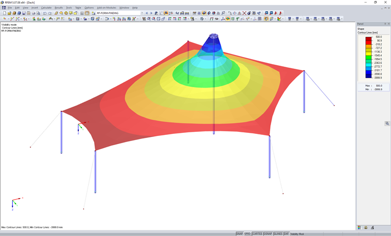
Results
After the FF calculation, the results are displayed under the "RF‑FORM‑FINDING" load case. The result navigator is the same as in the case of an usual structural design, only without the FF analysis. Deformation results describe the deformation between the initial input and the found equilibrium shape. Member and surface results show the force or stress conditions for the equilibrium shape, considering the defined FF parameters.
The "RF‑FORM‑FINDING" load case represents a new model configuration with the surface stress/prestress. A subsequent calculation with a specific surface load input, such as wind load, then uses the model described under the load case "RF‑FORM‑FINDING" as the initial configuration, with all the associated effects. In the case of these subsequent load cases, the deformation applies to the previously determined equilibrium shape.