


In the RF‑/STEEL EC3 add‑on module, the RF‑/STEEL Cold‑Formed Sections extension allows you to perform a local transverse force analysis for unstiffened webs according to [1] 6.1.7 (the module extension requires a separate license). This article presents the corresponding designs using the example of a bending beam made of a cold‑formed C‑section and subjected to a single load.
System and Load
A beam with a length of two meters consists of a cold‑formed C 2020 section made of S 235 steel. It is loaded with a single load of 10 kN at a distance of 50 cm from the support. The load acts in the shear center. The self‑weight is not considered.
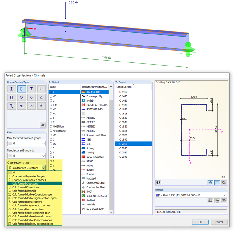
When selecting the section from the library, it is important to ensure that the cross‑section shape of the C‑section corresponds to the "Cold‑formed C‑sections" category. This condition can be set using the filter function. The RF‑/STEEL Cold‑Formed Sections module extension is designed for the design of cold‑formed sections: A rolled C or U section would not be designed according to [1].
Data Input in RF‑/STEEL Cold‑Formed Sections
In the RF‑/STEEL EC3 add‑on module, the specifications for a design according to EN 1993‑1‑3 [1] must be made in the "Details" dialog box, "Cold‑formed Sections" tab.
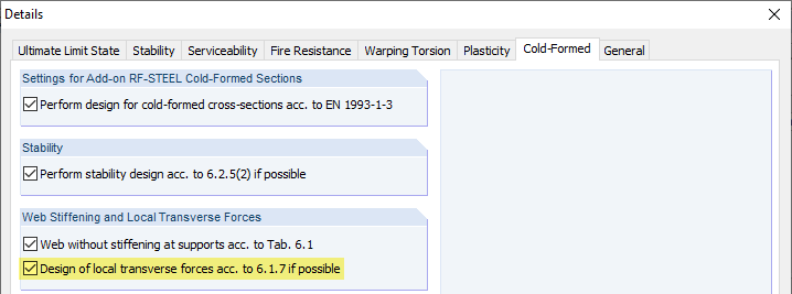
The "Check local transverse force according to 6.1.7, if possible" check box controls whether the program checks local failure modes in the web. If this option is activated, the boundary conditions, such as the length of the stiff bearing, can be defined in the "1.14 Local Transverse Forces" window.
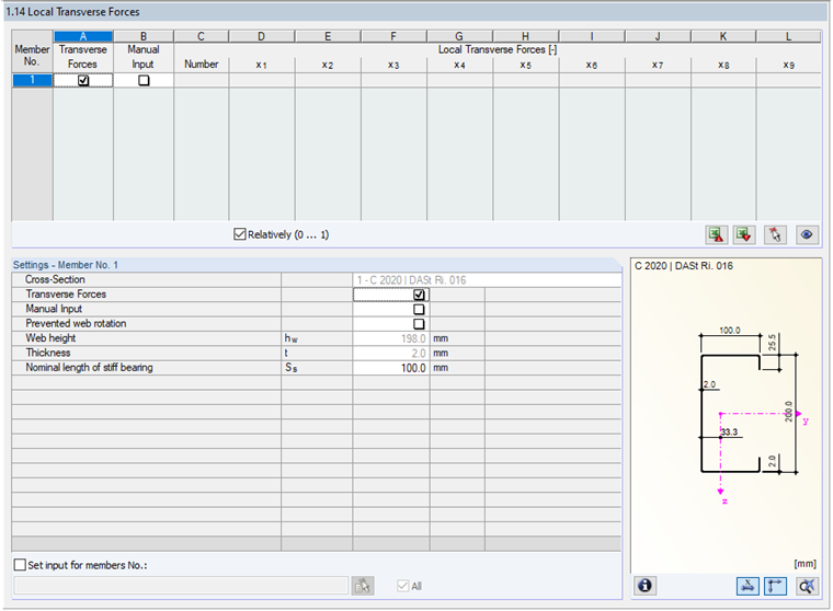
Consideration of the transverse loading is activated by default. The shear force distribution in the member is used for the design of the web stress due to local transverse force. The program examines all discontinuity points of the shear force. The "Nominal length of stiff bearing" is preset to 0.10 m.
Results in RF‑/STEEL EC3
The calculation of the effective cross‑section is performed iteratively in a maximum of two steps. Afterwards, the utilizations due to local transverse force are displayed with the designs. The details of each design can be viewed as "Intermediate Values".
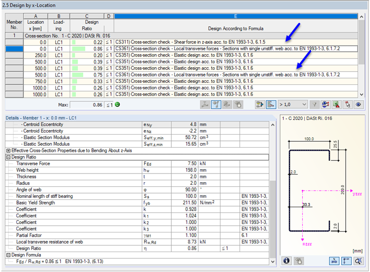
The design for local transverse force is performed at the two supports and at the load application point, according to the shear force distribution. The greatest utilization occurs at the location x = 0.00 m. The design for this location is as follows:
There is a support reaction at a cross‑section that has only one web. The C‑section with a plate thickness of t = 2.0 mm has stiffened flanges due to its lips. The distance of the support from the free end is 0.00 m and is thus less than 1.5 times the web height hw = 198 mm. Therefore, [1] Equation (6.15a) is governing for determining the web resistance Rw,Rd.
The following parameters must be applied:
This results in the following web resistance:
The design condition according to [1] Equation (6.13) is satisfied:
The design is performed analogously for the other two design locations.
Alternative: Manual Definition of Forces
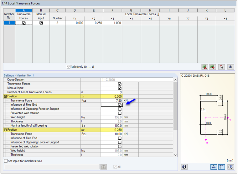
If the shear force distribution does not realistically represent the applied load, the locations of the load and the load magnitudes, including the nominal lengths of the stiff bearing, can be defined manually. This is exemplarily implemented in the attached RFEM model for Design Case 2.
For a manually defined force, no automatic comparison of the shear force effect for the support locations is performed. These locations must be defined individually with the respective support forces. In this case, the "Free end" check box must be activated as shown in Image 05. Only then is the distance c ≤ 1.5 hw considered and [1] Equation (6.15a) used for the design. Otherwise, [1] Equation (6.15d) would apply.
Summary
With the RF‑/STEEL Cold‑Formed Sections module extension for RF‑/STEEL EC3, you can, among other things, perform designs for local transverse force according to [1] Section 6.1.7. The design‑relevant locations are automatically determined from the shear force distribution for this purpose. Alternatively, it is possible to specify the forces manually. The design for local transverse force with RF‑/STEEL Cold‑Formed Sections is performed according to [1] 6.1.7.2 for cross‑sections with an unstiffened web or according to [1] 6.1.7.3 for cross‑sections with two or more unstiffened webs. Web cross‑sections with longitudinal stiffeners cannot be designed according to [1] 6.1.7.4.