


Theoretical Background
Designs 7.3.4 and 7.3.4 are usually performed for the external load. Both design checks are based on the formulas (7.9) and (7.11).
The crack width design is performed in the modules if the existing concrete stress is σc > fct,eff,wk and the concrete is cracked. You can adjust the value fct,eff,wk in the modules.
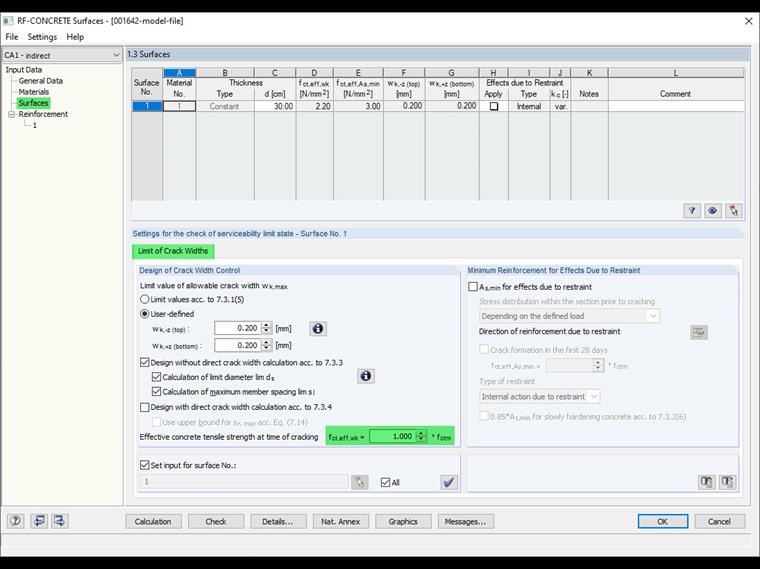
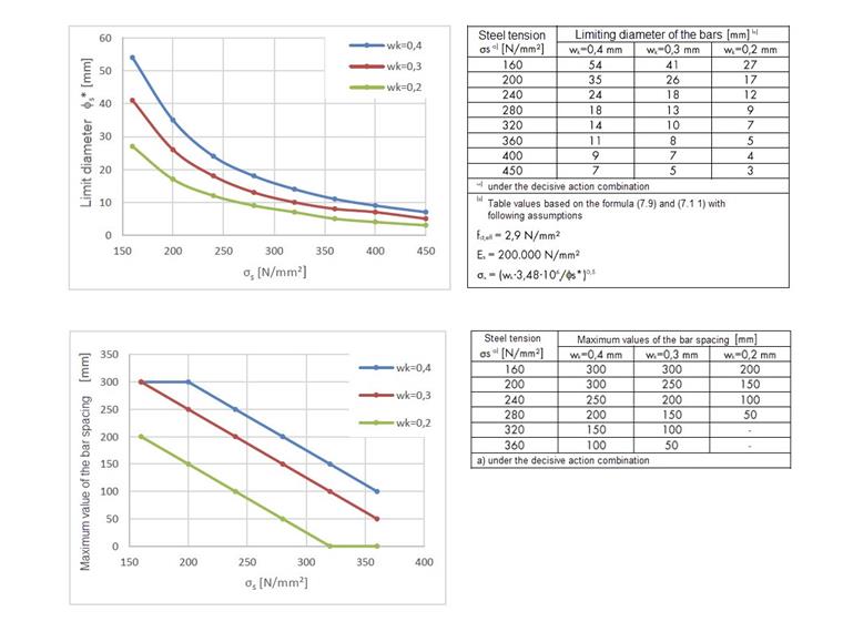
Table 7.2DE used for the indirect calculation is based on the limit values of (7.9) and (7.11), on assumptions for the tensile strength fct,eff, and for the modulus of elasticity Es. Based on these assumptions, the maximum allowable diameters depending on the steel stress are shown in Table 7.2.DE and the maximum values of the member spacings in 7.3N. Both tables are set up for an allowable crack width of 0.2 to 0.4 mm. Using a modified limit diameter, the values of the system to be considered are transferred to the values specified in Table 7.2DE.
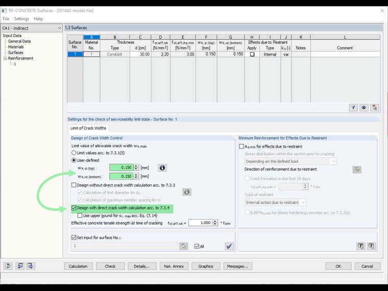
For the direct calculation, there are no limits for the allowable crack width because the crack width wk is always calculated directly. This also allows you to apply a limit value of the crack width < 0.2 mm.
Utilizing in RF-CONCRETE
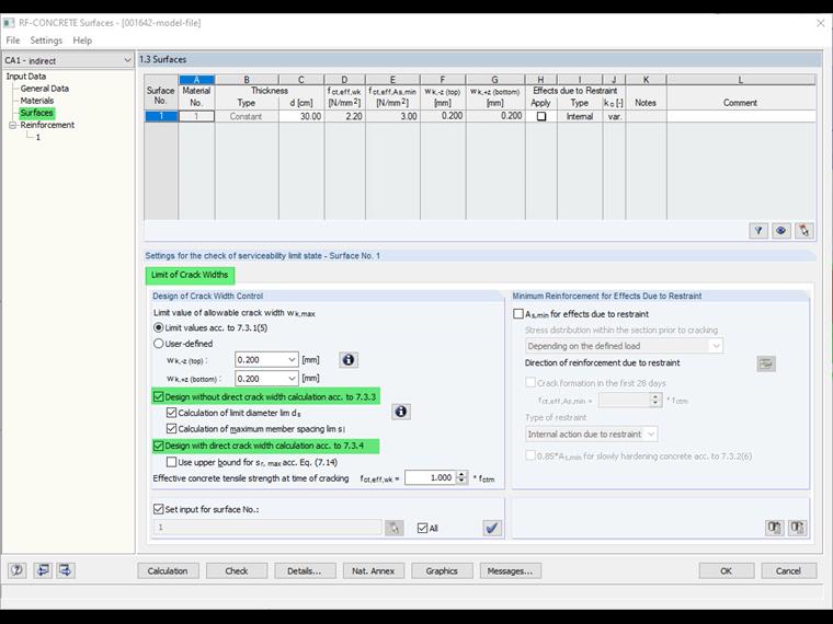
Both methods are available in the RF-CONCRETE Members and RF-CONCRETE Surfaces add-on modules. According to the default setting, both methods are active. Theoretically, it is unnecessary to perform both designs. It is sufficient if one of the two designs is fulfilled. Nevertheless, there is a specific reason that both designs are activated by default. This point, the economic reinforcement for the crack width design, will be described in the following text.
Finding Economical Reinforcement for Crack Width Design
The "Find the most economical reinforcement for crack width design" option is available in RF-CONCRETE Members and RF-CONCRETE Surfaces. The reason for this option is as follows.
According to DIN EN 1992 7.3.3 (2), exceeding the crack widths is unlikely if the minimum reinforcement according to 7.3.2 is met, and at the same time,
- For cracks due to predominant restraint, the member diameter according to Table 7.2N is observed. In this case, you have to use the value immediately after cracking for the steel stress (for example, use σs in Equation [7.1]).
- The conditions according to Table 7.2N or Table 7.3N are met for cracks due to predominantly direct actions. The steel stresses are usually determined on the basis of cracked cross-sections under the governing action combination.
This means that not all parts of the indirect calculation have to be fulfilled if it is ensured at the same time that the minimum reinforcement is met. This may result in the required reinforcement determined in the course of the direct calculation not being the most economical reinforcement. This is also the reason that both designs are active by default.

Crack Width Design for Allowable Crack Width < 0.2 mm
Due to the situation of the presetting mentioned above, there may be a problem in the design of an allowable crack width < 0.2 mm. For the range wk < 0.2 mm, the tables on which the indirect calculation is based are irrelevant. In this context, the indirect calculation must be deactivated for such a situation and only be verified with the direct calculation.
Calculation Performance
The question of the computing speed sometimes arises, particularly with regard to the situation when both designs are performed according to the default setting. In this regard, the additionally performed design has no major influence on the calculation. The determination of the required reinforcement for the crack width design is performed iteratively. If a design is not fulfilled, an additional rebar is assigned to the required reinforcement and the design is performed again. This is done until either no more members can be inserted into the cross-section, or the applied design criteria are fulfilled.
Crack Width Design for Restraint
The RF-CONCRETE add-on modules are designed in such a way that the minimum reinforcement according to 7.3.2 is determined for the imposed stress. Insofar as it is feasible that the loading due to restraint can be displayed on the load side, the crack width design for the restraint can also be performed by means of the crack width calculation.
