


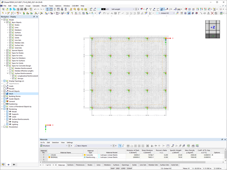
The bending design of the reinforced concrete slab is performed while taking into account the standard requirements of Eurocode 2. First, the calculation is carried out with Q335A mesh as a basic surface reinforcement for the top and bottom layouts.
Once the design details are available, the reinforcement is complemented by a rebar reinforcement with a diameter of 16 mm for areas that are not covered by the mesh basic reinforcement.
Loading
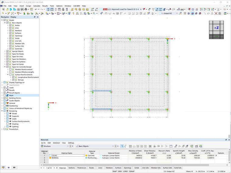
The loading in this example is applied according to Eurocode 1. In addition to the self-weight, a permanent load of 1.25 kN/m² is applied to the whole surface. The imposed load, including the boundary wall allowance of qk,1=3.25 kN/m² (Category A "Residential Areas", according to Eurocode 1), is applied in a separate load case for each panel (Image 3). The combination of the actions for the ultimate limit state is done for the permanent and transient design situation according to Eurocode 0.
Input Data for Concrete Design
The design of concrete elements in RFEM 6 can be initiated by activating the Concrete Design add-on in the model’s Base Data. In this manner, elements can be considered for design via the Design Properties check box, as shown in Image 4.
This is very convenient because the modeling and design parameters of the slab can be defined simultaneously in the associated tabs. The concrete design input data can also be displayed and edited in the table section.
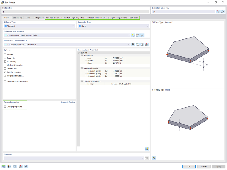
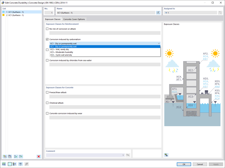
First, the concrete cover of the surface can be defined according to the standard. Exposure classes for both the reinforcement and the concrete, as well as other concrete cover options, are available in the Concrete Durability dialog box (Image 5). In this example, exposure class XC1 is set for the reinforcement.
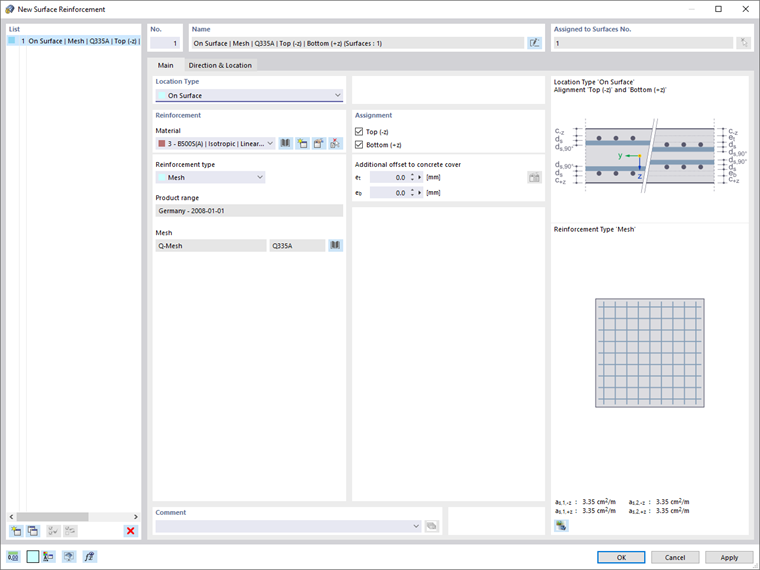
The Concrete Design Properties tab allows the first reinforcement directions to be set. For both the top and bottom surface sides, the first reinforcement direction is in the local x-direction of the surface. The basic reinforcement can be defined via the New Surface Reinforcement dialog in the Surface Reinforcement tab (Image 6). At this point, Q335A mesh is assigned as a basic surface reinforcement for the top and bottom of the whole surface. The reinforcement direction is as,1 for both.
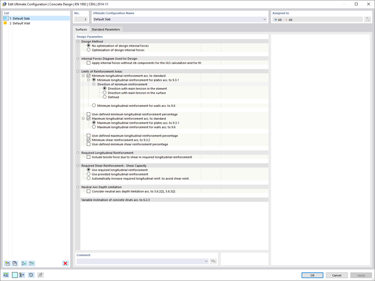
It is important to mention that the design parameters can also be adjusted in the Design Configurations tab. The parameters for the ultimate design configuration are illustrated in Image 7.
Results
The design details, which can be opened in the Concrete Design table, allow a pointwise evaluation of the results. They contain, among other things, information about the governing internal forces by surface, the design ratios, and the design check type, as well as the reinforcement on the surface.
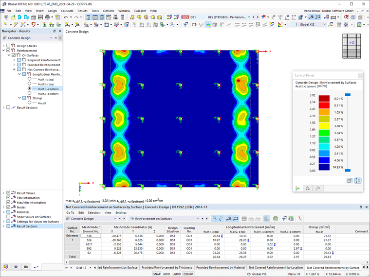
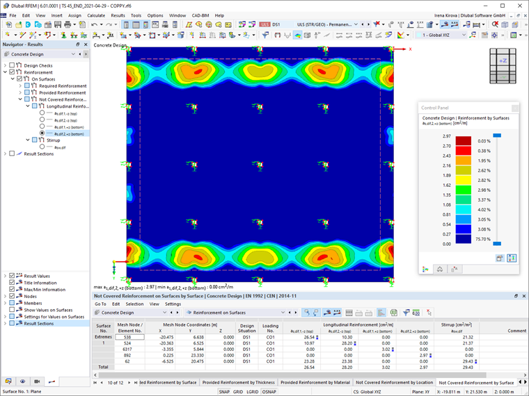
The Concrete Design results can also be evaluated graphically in the RFEM work window. As a matter of fact, it is possible to display separately the required reinforcement, the basic reinforcement, and the reinforcement that is not covered. This can be done for the individual reinforcement layouts and directions, as shown in Image 8.
The design ratios and the reinforcement on the surface can easily be exported in the printout report. Furthermore, these results can serve to consider additional reinforcement for areas that are not covered by the basic mesh reinforcement.
Hence, the results in terms of Not Covered Reinforcement can be displayed to illustrate the areas where an additional rebar reinforcement should be placed. As Images 8 and 9 show, these areas are the edge panels above the columns.
Assigning Additional Rebar Reinforcement
Additional rebar reinforcement for areas that are not covered by the basic mesh reinforcement can be assigned via the Data tab of the Navigator or via the surface’s Edit Window as before.
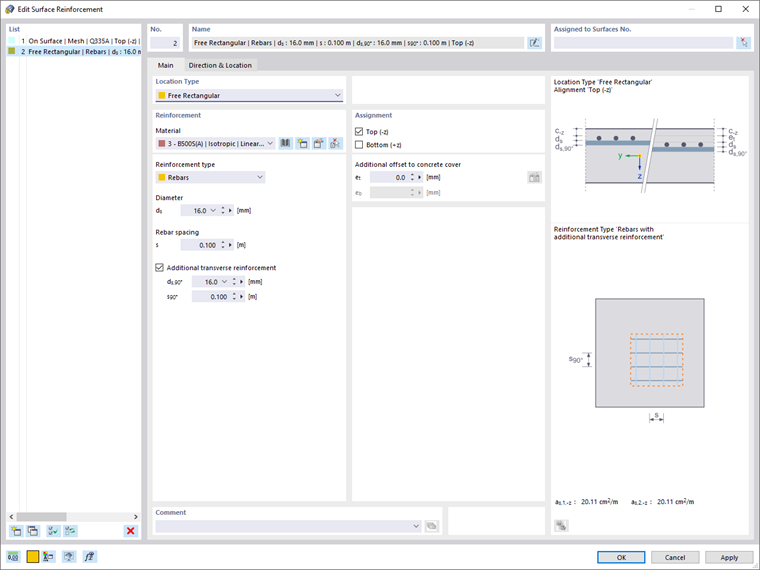
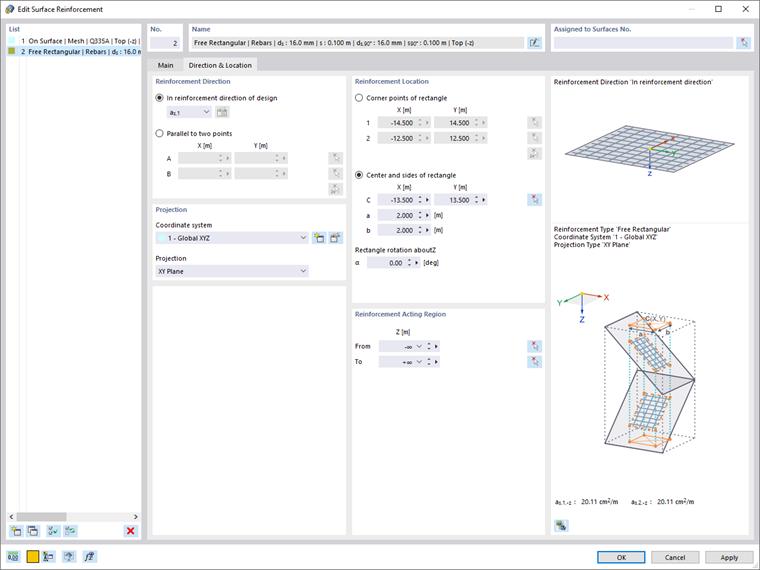
The existing basic reinforcement is now complemented by a free rectangular rebar reinforcement on the top side together with an additional transverse reinforcement with the same diameter and spacing (Image 10). The location of the additional reinforcement can be defined by selecting the corner points or the center and sides of the area of interest (Image 11).
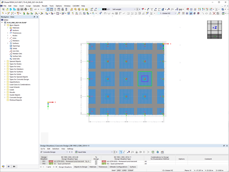
In this example, rebars with Ø 16 at a distance of 10 cm are placed at both the larger and smaller areas of the columns (Image 12). It is to be noted that the reinforcement defined for one location can be straightforwardly assigned to the other areas of interest using common RFEM 6 functions such as copy, mirror, and rotate.
Final Remarks
The design of concrete slabs in RFEM 6 can be initiated by activating the Concrete Design add-on in the model’s Base Data. The surface of interest can be considered for design by selecting the Design properties check box. This allows the user to define the concrete cover, concrete design parameters, surface reinforcement (shear and longitudinal reinforcement), and the design configurations.
Once the calculation has been carried out, the Concrete Design results can be evaluated in both tabular and graphical form. In addition to the design ratios, it is possible to display the required reinforcement, provided reinforcement, and not covered reinforcement separately for the individual layouts and directions. Finally, these results can serve to define additional reinforcement for areas that are not covered by the basic mesh reinforcement.