Stability Requirements
In Sec. C1 [1], five requirements are listed when considering the stability design of a steel structure. Directly from AISC 360-16, these include:
- Flexural, shear, and axial member deformations, and all other component and connection deformations that contribute to the displacements of the structure
- Second-order effects (including P-Δ and P-δ effects)
- Geometric imperfections
- Stiffness reductions due to inelasticity, including the effect of partial yielding of the cross-section, which may be accentuated by the presence of residual stresses
- Uncertainty in system, member, and connection strength and stiffness
The direct analysis method of design can be used to meet the above requirements. This article will focus primarily on items b through d and the application in RFEM 6.
Second-Order Effects
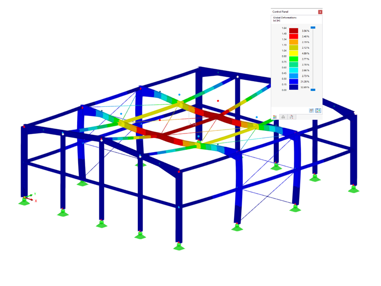
The structure analysis shall consider second-order effects including P-Δ and P-δ. When a structural element such as a column has an applied axial load in addition to an applied lateral load, the element will deflect. The deflection distance, Δ, multiplied by the applied axial load, P, creates a secondary moment termed P-Δ that must be considered. Additionally, the destabilizing effects of the axial load acting along the member’s deflected curvature, or P-δ, should also be considered in the analysis. Fig. C-C2.1 [1] provides a graphical example of these secondary effects on a member.
The AISC lists the conditions under C2.1(b) [1] where P-δ effects can be neglected altogether. Otherwise, if a member is subject to both compression and flexure, these localized deformations should be considered in the analysis.
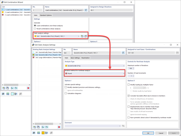
Within RFEM 6, the second-order analysis is solved iteratively as a sequence of linear problems where the axial force is updated from the previous iteration and considered constant within the iteration step. This numerical approach is the fixed-point iteration method known as the Picard method. Both P-Δ and P-δ secondary effects are captured automatically in the underlying differential equations within the RFEM 6 solver when set to this method.
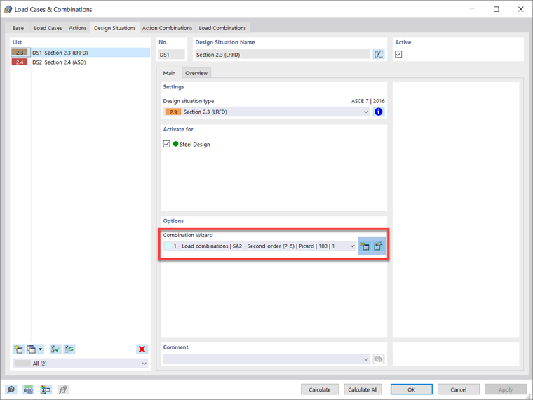
Design situations and load combinations in RFEM 6 are set by default to second-order and the Picard method. The user can modify these default settings for the LRFD or ASD design situations, for example, under Combination Wizard – Static analysis settings – Iterative method for nonlinear analysis.
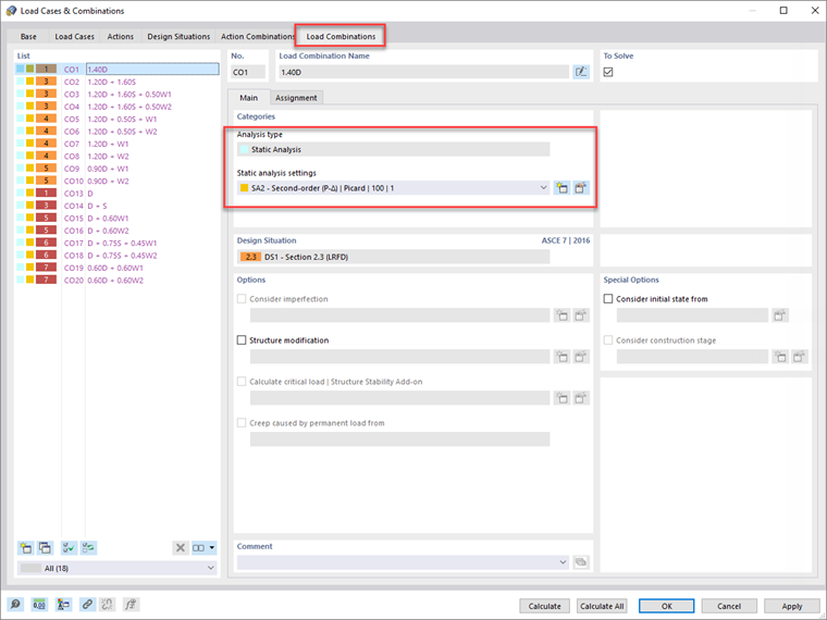
The individual load combinations will subsequently follow the analysis settings defined under the respective design situation. However, the user can modify the load combination settings individually, if preferred.
To comply with Sec. C2.1(b) [1], the user can keep the default second-order analysis for Design Situation 1 – LRFD to be used for strength design. Additionally, the analysis type desired can be set for Design Situation 2 - ASD, which may be used for serviceability checks along with any other design situations created. Visit the RFEM 6 online manual Static Analysis Settings for further information on the options offered within these dialog boxes.
Geometric Imperfections
Sec. C2.2 [1] requires structure imperfections to be considered either by direct modeling of the imperfections or the use of notional loads. The AISC further clarifies the main concern for imperfections in building structures is column out-of-plumbness. Member out-of-straightness is not required in this section, as this effect is accounted for in Ch. E [1] for compression design.
Direct modeling of imperfections should consider initial displacements to due to loading and anticipated buckling mode shapes applied to give the greatest destabilizing effect. Depending on the structure size, this could be time-consuming and complicated. The alternative method with applied notional loads can instead be used.
According to C2.2b(a) [1], notional loads should be applied as additive lateral loads at all levels in all load combinations. The exception given in C2.2b(d) [1] includes when the structure’s second-order drift to first-order drift is equal to or less than 1.7; then the notional loads may be applied to the gravity-only load combinations and excluded from combinations with other applied lateral loads.
The notional load magnitude at each level can be calculated using Equation C2-1 [1].
|
α |
= 1.0 (LRFD); 1.60 (ASD) |
|
Ni |
Notional load applied at level i, kips (N) |
|
Yi |
Gravity load applied at level i from the LRFD load combination or ASD load combination, as applicable, kips (N) |
Notional loads should be applied in the direction that causes the greatest destabilizing effect. This means that for gravity-only load combinations, notional loads should be applied in both orthogonal directions. For load combinations with applied lateral loads, the notional loads should be applied in the same lateral load resultant direction (for example, wind loads in the X-direction should include notional loads in the X-direction).
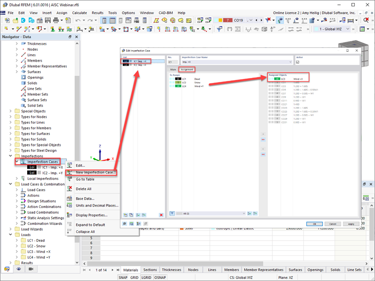
RFEM 6 provides users with the ability to define imperfection cases in the orthogonal directions, such as in the ±X or ±Y directions. The load case(s) can further be assigned to each imperfection load case, taking into consideration the greatest destabilizing effect. RFEM will automatically assign the imperfection case to the generated load combinations, as shown directly in this dialog box.
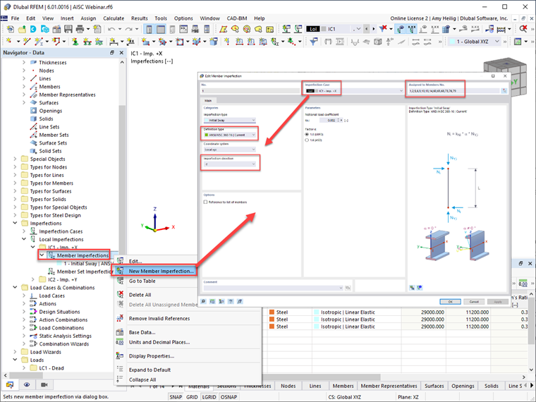
Once the imperfection cases have been defined, the user must define the member imperfections under each imperfection case. The “ANSI/AISC 360-16 | Current” available in the drop-down menu will consider the member’s axial force from the assigned load combination, utilize Eqn. C2-1 [1], and apply the calculated notional load magnitude at both the member start and end.
The “ANSI/AISC 360-16 | Gravity Load” will allow the user to refer to a different load combination other than the current to calculate the member’s axial force. The imperfection direction based on either the global axes or member local axes should also be specified. Careful consideration should be given to the imperfection direction, as the intent is to apply in the overall structure direction to cause the greatest destabilizing effect. Once this information is defined, the imperfection can be assigned to multiple members, such as all columns in the structure.
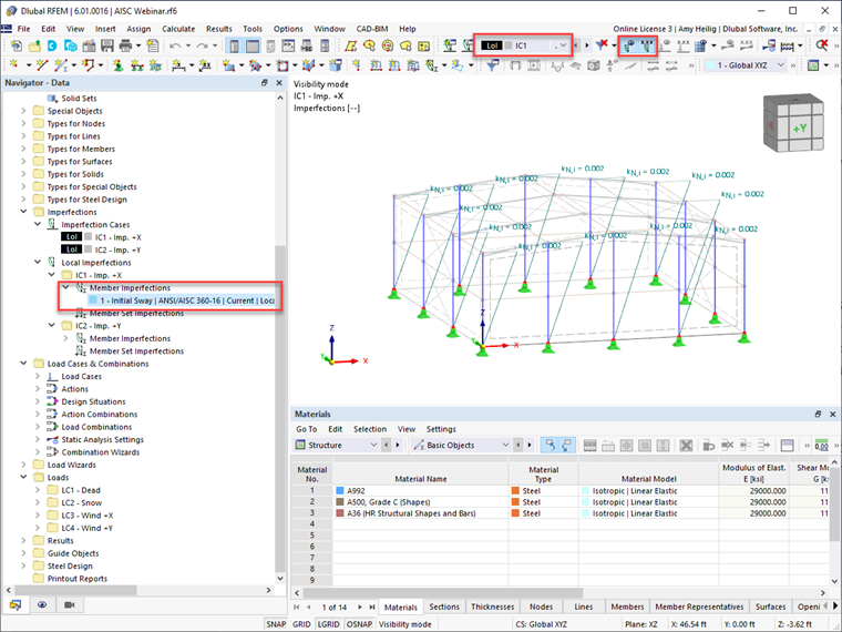
Once the imperfections are applied, they can be seen graphically displayed on the structure in RFEM.
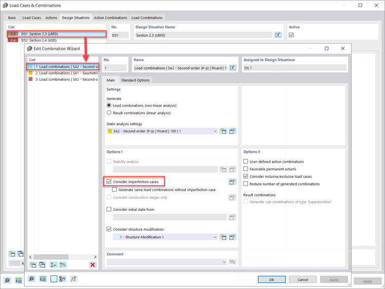
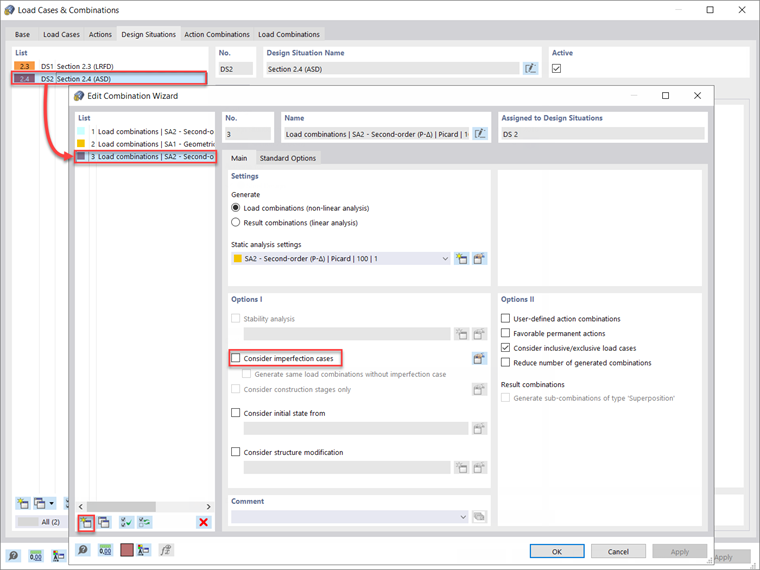
Imperfections should only be applied to the strength load combinations and are not required for serviceability checks. Therefore, under the Edit Combination Wizard dialog box shown previously in Image 1, “Consider imperfection cases” should be turned on and applied to Design Situation 1 - LRFD assuming the strength design will be carried out according to the LRFD method.
Alternatively, the “Create New Combination Wizard” button in the lower left can be used to generate a new item definition with “Consider imperfection cases” turned off. The static analysis settings will be set to second-order (P-Δ) for this example’s serviceability design similar to the strength design. Now, this new Combination Wizard can be assigned to Design Situation 2 – ASD assuming serviceability design will be carried out using the unfactored load combinations.
Once these settings are applied to the design situations, the individual load combinations listed under the “Load Combinations” tab will also reflect these same settings automatically.
Adjustments to Stiffness
Member residual stresses can lead to partial yielding of the cross-section, producing a general softening of the structure. This in turn leads to destabilizing effects. Additionally, the spread of plasticity through the member cross-section and along the member length should be considered.
To approximate these effects on the member strength reduction, the AISC has required a 0.8 factor to be applied to all stiffnesses that contribute to the stability of the structure. The standard goes on to state in C2.3(a) [1], stiffness reductions should be applied to all members to avoid artificial distortion of the structure. Therefore, this 0.8 factor can be applied to all members’ axial and flexural stiffnesses.
Additionally, the τb factor calculated from Eqns. C2.2a and C2.2b [1] shown below should be applied to the members’ flexural stiffness only. Consideration must be given to slender vs. nonslender-element sections for the cross-section compressive strength.
- When αPr/Pns ≤ 0.5
- When αPr/Pns > 0.5
α
= 1.0 (LRFD); 1.60 (ASD)
Pr
Required axial compressive strength using LRFD load combination or ASD load combinations, kips (N)
Pns
Cross-section compressive strength;
for nonslender-element sections: Pns = FyAg,
for slender-element sections: Pns= FyAe,
where Ae is as defined in Section E7, kips (N)
According to Sec. C2.3(c) [1], it is permissible to set τb = 1.0 for all members’ flexural stiffnesses, but an additional notional load should be applied to the structure defined by this section. Additionally, stiffness reductions are only applied to strength and stability limit states. It is not applicable to serviceability limit states or other analyses such as drift, deflection, vibration, and period determination.
RFEM 6 gives users the ability to apply the AISC stiffness reduction requirements to selected members. The 0.8 factor is applied to the member axial and flexural stiffness, while the τb factor can be automatically calculated from Eqns. C2.2a and C2.2b [1] and applied to the member flexural stiffness.
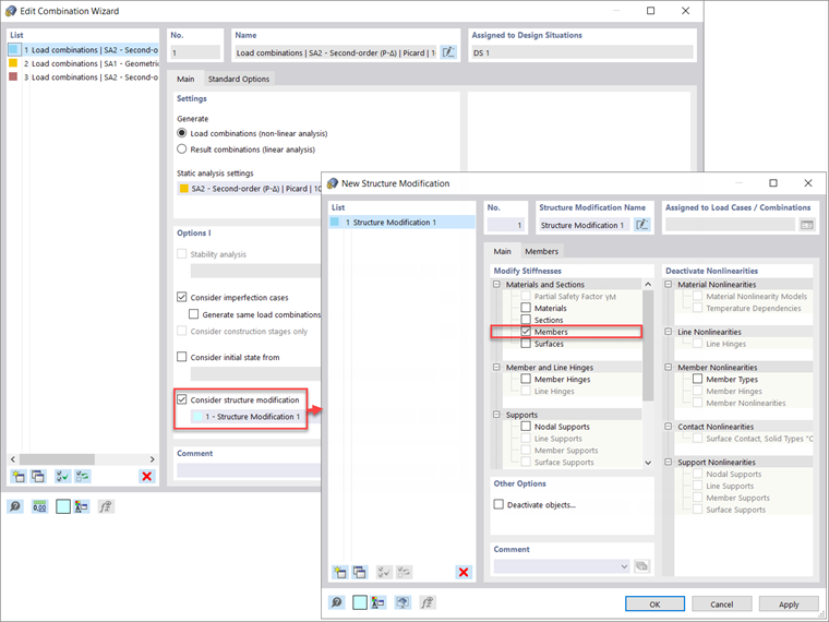
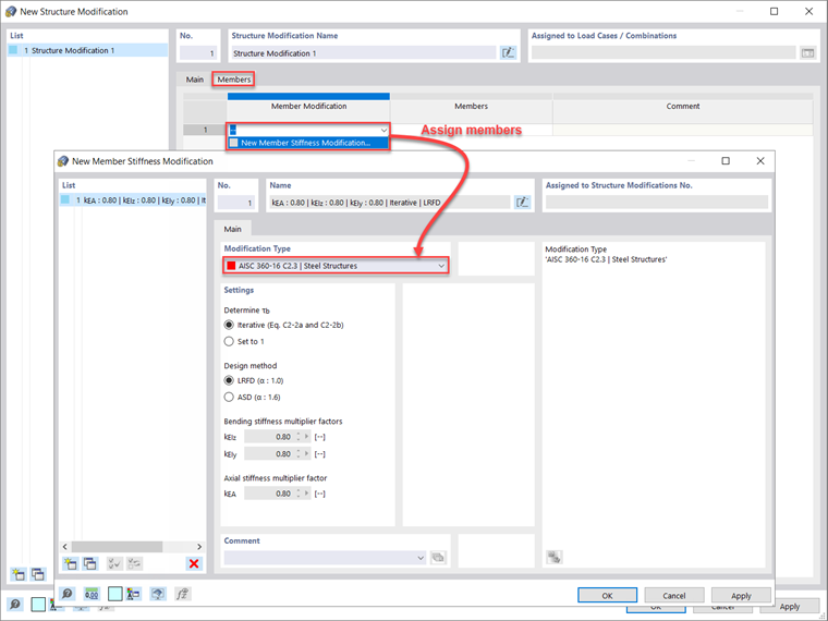
Revisiting the Combination Wizard for Design Situation 1 – LRFD, the “Consider structure modification” should be activated with a new structure modification setting defined. Once the “Members” option is also activated, a new Members tab is available. Within this new tab, the “New Member Stiffness Modification” can be selected. This brings up the final option to select the “AISC 360-16 C2.3 | Steel Structures” from the drop-down menu. Notice that the “Iterative Eqs. C2-2a and C2-2b” is selected to automatically calculate the flexural stiffness τb factor based on either the slender or nonslender elements normal force. The 0.8 factor is set by default and applied to the bending and axial stiffness. Once all options are defined, the steel members to which the stiffness reduction should be applied are selected either graphically, or the member numbers can be directly input back into the Structure Modification dialog box.
Note that the separate Combination Wizard which was previously defined for Design Situation 2 – ASD to deactivate the imperfection options for serviceability design described above should also leave the “Consider structure modification” unchecked. This will utilize the full member stiffnesses for all unfactored load combinations.
Concluding Remarks
The requirements given in AISC 360-16 Ch. C for the direct analysis method, including second-order effects, member imperfections, and stiffness reductions, can be considered in the RFEM 6 analysis and design using the workflows described above. For more information and examples on the direct analysis method application in RFEM, refer to the previously recorded webinar AISC 360-16 Steel Design in RFEM 6 and download the related model under Models to Download.
- Webinar | AISC 360-16 Steel Design in RFEM 6 (USA)
- Model to Download | Steel Hall Structure | AISC 360-16