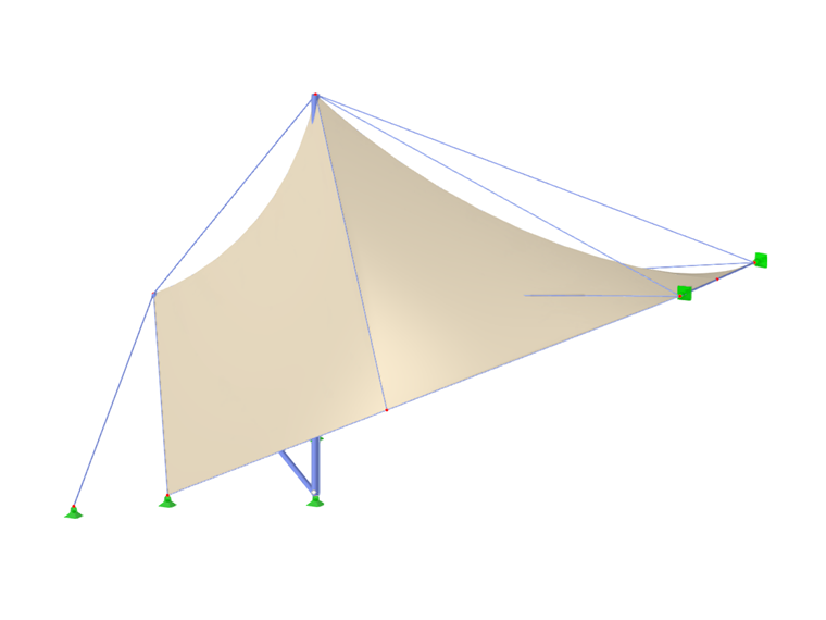
The Stress-Strain Analysis add-on is available for activation in the Base Data of the model (Image 1). Once you activate the add-on, the navigator, tables, and dialog boxes are extended with new entries that are fully integrated into the user interface of RFEM/RSTAB.
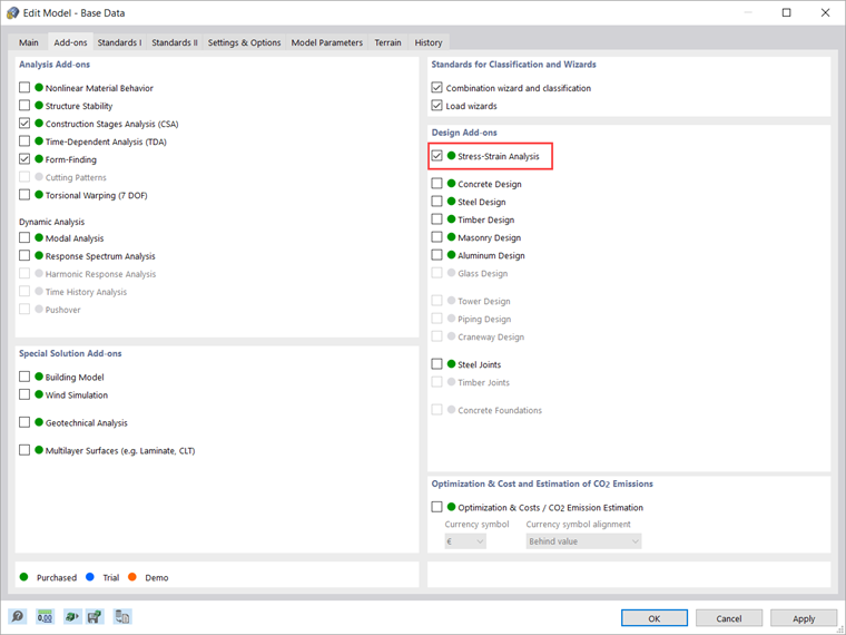
This article will show a practical example of how to manage the input data for member and surface configurations and perform the stress-strain analysis in RFEM 6. The stress-strain analysis will be performed for a segment of a stadium roof made of membranes, shown in Image 2. This way, you can check whether its elements (which were modeled in the program beforehand) meet the design requirements, or whether their properties must be revised (for example, regarding cross-section, material, thickness, and so on).
As already mentioned, the objects of the Stress-Strain Analysis category are available both in the navigator and in the table to define the input data for the design. Hence, you can check the objects to be designed as well as their materials and cross-sections. Depending on the selected object, specific configurations where you can specify limit values and other design options can be defined as well.
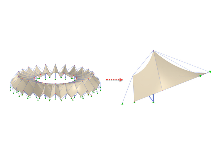
Given that this model consists of members and surfaces, specific tables for each of these object types are available in the stress-strain analysis settings. The configuration settings can be accessed via the "Open editing dialog box" icon (Image 3) where you can create different types for each design configuration and assign the appropriate configuration to each object.
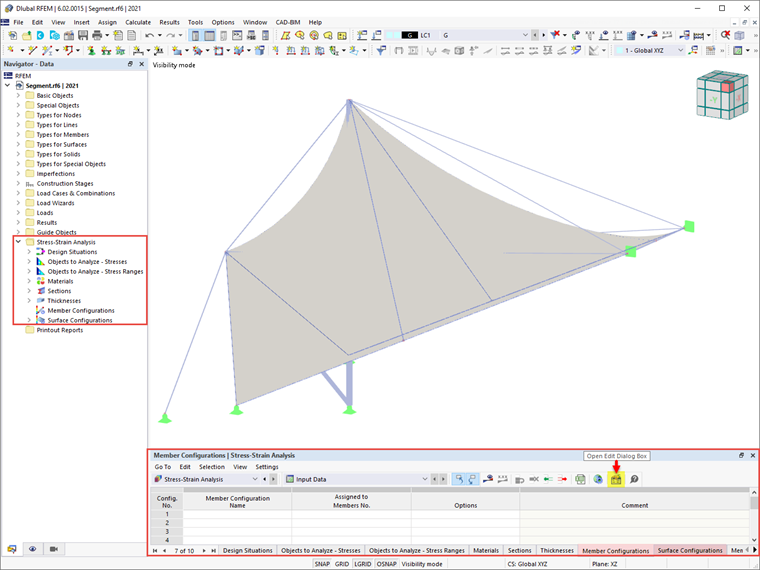
First, you can create a new member configuration based on the default values of the selected design standard. To do so, you can use the "New" button positioned below the list, which shows all configurations of this limit state available in the model. Since no configuration has been defined yet, this list is empty (Image 4).
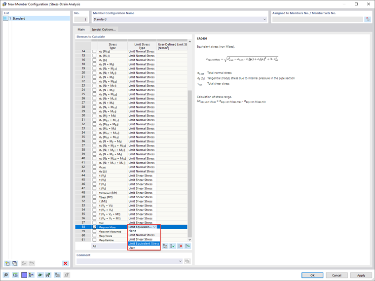
You can start defining the design configuration in the "Main" tab of the dialog box by selecting the stresses to be calculated and specifying the limit stresses for comparison. For instance, you can choose between limiting normal, shear, or equivalent stress, as well as specifying a user-defined limit stress. In this example, the equivalent von Mises stress will be selected for calculation, and you can see the associated formula in the right part of the dialog box.
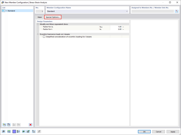
Other design-relevant options can be found in the "Special Options" tab shown in Image 5. Hence, you can modify the weighting of the normal and shear stresses in the von Mises equivalent stress by specifying the kσx, and kτ factors, respectively.
If transverse loads are applied to the upper chord of beams, it is also possible to consider the eccentrically acting transverse loads by a simplified method for I-sections with which the bending moment Mz is completely applied to the top flange for each rolled or parametric symmetric I-section of the design case.
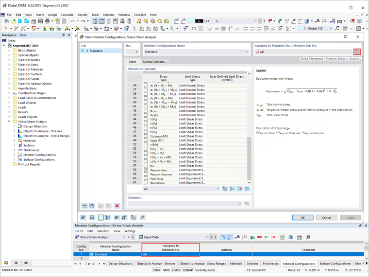
Once the configuration is defined, you can assign it to the respective objects via the "Select Individually" button in the dialog box at the top right, or directly in the input table of the stress-strain calculation for the corresponding configuration (Image 6). Furthermore, you can create multiple configurations and assign them to different objects.
The specifications within a configuration apply to all objects to which this configuration is assigned. If no configuration is assigned to an object to be designed, no designs are performed for this object.
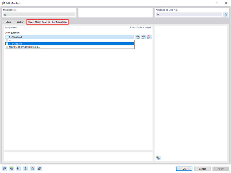
The design configurations are also included in the Edit Dialog box of the individual members, as shown in Image 7. The assignment can be done in the Design Configurations tab of the dialog box, where you can select an existing configuration from the list, use the "New" button to create a new configuration, or use the "Multiple Selection" button to graphically select another object from which the respective configuration is imported. The edit menu of the selected configuration can be opened via the "Edit" button.
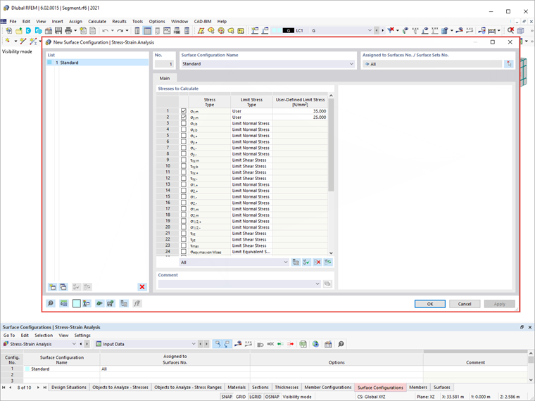
In the same fashion, you can define surface configurations via the Stress-Strain Analysis table, or the edit dialog box of the specific surfaces. You can select the stresses to be calculated and specify the limit stresses as shown in Image 8. To specify a user-defined limit stress, select the limit stress type "User". This activates the "User-Defined Limit Stress", where you can define the values of interest.
Other settings for the stress-strain analysis will be defined in upcoming Knowledge Base articles. However, if you perform the analysis with the above-defined member and surface configurations, you will obtain the results as shown in Image 9.
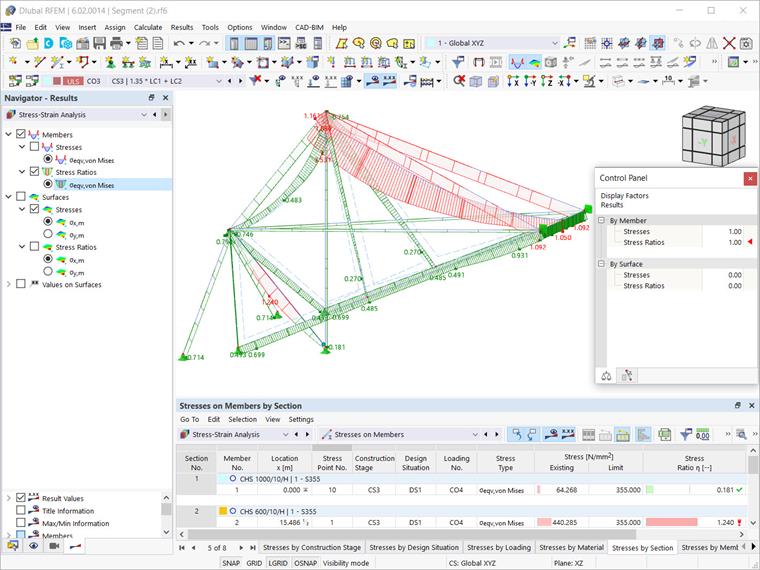
The results are available in both graphical and tabular form. You can select the specific results to be displayed in the Result navigator, whereas detail results for members and surfaces can be found in the Stress-Strain Analysis table. This way, you can check whether the elements meet the design verifications or whether they need to be edited in terms of cross-section, material, thickness, and so on.