


The designed foundation is a bucket foundation with rough bucket sides. The connected column has a rectangular cross-section with dimensions of 30 cm × 40 cm. The design is based on DIN EN 1992-1-1. The materials used are concrete with the strength class C 35/45 and reinforcing steel of the type B500S(A). The concrete cover complies with the minimum requirements of the standard, designed for exposure classes XC3 for construction on prepared ground.
Dimensions of Foundation Slab and Bucket
All dimensions are specified in the Geometry tab. The slab has a width of 3.30 m, a length of 2.60 m, and a thickness of 0.36 m. The bucket has a height of 1.31 m; the embedment depth of the column is also 1.31 m. The eccentricity of the column in the x-direction is −0.30 m, related to the center of the foundation plate.


There are two options for arranging the horizontal stirrups in the bucket:
- Stirrups that enclose the column
- Stirrups that lie completely within a bucket wall
Enclosing stirrups are used in this example. The ‘’'Reinforcement'‘’ tab includes the specifications on the reinforcing steel material, the reinforcement type of the slab, and the arrangement type of the horizontal stirrups in the bucket.

Load Cases
The internal forces of the following load cases are available for the ultimate limit state design:
| Load Case | PZ,d [kN] | PX,d [kN] | PY,d [kN] | MX,d [kNm] | MY,d [kNm] |
| 1 | 300 | -50 | 20 | 100 | 250 |
| 2 | 100 | 0 | 0 | 0 | 327 |
| 3 | 500 | 0 | 0 | 150 | -150 |
Required Bucket Reinforcement
Required Outer Horizontal Reinforcement
Load Combination 1 (LC1+LC2) results in the largest required reinforcement area of the horizontal outer stirrups in the bucket and is thus governing. The horizontal forces on the bucket walls are as follows:
This stirrup is subjected to tension due to two different actions: On one hand, a tensile force arises from the bending of the bucket wall, which is perpendicular to the considered horizontal force. On the other hand, a tensile force acts through the direct tensile stress of the wall, aligned parallel to the considered horizontal force.
From the horizontal force Ht,x, two tensile forces in the outer stirrups result:
- In the wall in the x-direction, the tensile force TH,x arises from tensile stress.
- In the wall in the y-direction, the tensile force TH,out,x(Wall) results from bending of this orthogonal wall.
Similarly, from the horizontal force Ht,y:
- In the wall in the y-direction, the tensile force TH,y arises from tensile stress.
- In the wall in the x-direction, the tensile force TH,out,y(Wall) results from bending of this orthogonal wall.

For determining the maximum tensile force in the stirrup, you need to add the effects of both bending and tension. This is necessary, because their causes – that is, simultaneously acting horizontal components (Ht,x and Ht,y) – originate from the same load case and are thus effective simultaneously.
Required Reinforcement Area of Horizontal Stirrups in Bucket Due to Tension in x-Direction
The upper horizontal force Ht,x can be divided in such a way that each half acts at the quarter points of the column's length in the y-direction.

The proportional tensile force in the outer stirrups is then:
Thus, the required reinforcement area of the horizontal stirrups in the bucket due to the tensile force in the x-direction is:
Required Reinforcement Area of Horizontal Stirrups in Bucket Due to Tension in y-Direction
The required reinforcement area of the horizontal stirrups in the bucket due to the tensile force in y-direction Ht,y is determined similarly as Ht,x:
Required Reinforcement Area of Outer Horizontal Stirrups in Bucket Due to Bending of Ht,x
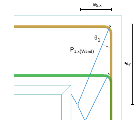
Considering the upper right corner alone (see the image above), it must be in force equilibrium. The horizontal inner forces must be balanced with the outer, loading horizontal force. Since no vertical outer forces act in the section considered here, it is now necessary to find a moment equilibrium. First, the sum of the moments about the point P is calculated. For this, the lever arms are determined:
The moment about the point P is then calculated as:
This bending design moment MEd must be balanced by an opposing moment. This is generated by the concrete compression force on the compressed inner side of the bucket wall in the y-direction with the lever arm z to the rotation point P. To determine the required concrete compression, proceed as follows:
- It is assumed that the concrete stress is uniformly distributed over the compression area.
- Starting from a concrete strain of 0.0 ‰, it is incrementally increased until the resulting internal moment equals the bending design moment MEd.
At the same time, it is assumed that the steel on the outer side of the bucket wall has already reached its maximum strain. Once the calculated internal moment exceeds the bending design moment MEd, the iteration is stopped.
At the end of the iteration, the following values were obtained:
| Designation | Value |
| Required reinforcement area As,w,req | 5.60 cm² |
| Bending design moment MEd | 52.02 kNm |
| Lever arm of internal forces z | 0.21 m |
| Used neutral axis depth x | 0.04 m |
| Reinforcement strain on tension side εs | 18.90 ‰ |
| Reinforcement stress on tension side σs | 449.899 N/mm² |
| Reinforcement strain on compression side εs,c | 1.2 ‰ |
| Reinforcement stress on compression side σs,c | 247.515 N/mm² |
| Concrete strain on compression side εc | -3.5 ‰ |
| Concrete stress on compression side σc | -19.833 N/mm² |
| Concrete compression force Fc | 252.07 kN |
| Tensile force Fs | 252.07 kN |
The required reinforcement area in the bucket due to the bending is 5.60 cm². This bending tensile force does not distribute evenly over both horizontal stirrups, but follows the compression strut mechanism. More information can be found in the Concrete Foundations manual.
To determine the tension component absorbed by the outer bucket stirrup, follow these steps:
- Determine the vertical and horizontal leg of the concrete compression strut within the bucket wall:
- Distribution angle of the load within the bucket wall:
- Proportional compression force in outer stirrups due to bending of the bucket wall:
- Proportional tensile force in outer stirrups due to bending of the bucket wall:
- The required reinforcement area of the outer horizontal stirrups in the bucket due to bending of Ht,x is:
Similarly to the bucket wall in the y-direction, the bending failure of the bucket wall in the x-direction due to HT,y is calculated, and the required reinforcement area of the outer horizontal stirrups in the bucket due to the bending of Ht,y Asw,h,out,erf(MEd|Ht,y) is determined. It results to 0.76 cm².
As explained above, it is necessary to add both bending and tension components to determine the required reinforcement area of the outer horizontal stirrups in the bucket:
- The required reinforcement area of the outer horizontal stirrups in the bucket due to the bending of Ht,x Asw,h,out,req(MEd|Ht,x) is added to the required reinforcement area of the horizontal stirrups in the bucket due to the tensile force in the y-direction Asw,h,req(Ht,y).
- The required reinforcement area of the outer horizontal stirrups in the bucket due to the bending of Ht,y Asw,h,out,req(MEd|Ht,y) is added to the required reinforcement area of the horizontal stirrups in the bucket due to the tensile force in the x-direction Asw,h,req(Ht,x).
Required Horizontal Reinforcement in y-Direction
First, consider the horizontal stirrup located on the outer side of the bucket wall in the y-direction. Load Combination 2 (LC1+LC3) results in the largest required reinforcement area of the horizontal stirrups in the y-direction and is thus governing.

As seen in the image above, it is assumed that only horizontal forces in the x-direction lead to tensile forces in this stirrup. For more information, see the Concrete Foundations manual.
The required reinforcement area of the horizontal stirrups in the y-direction in the bucket due to the bending of Ht,x is determined from the total required bending reinforcement of the wall in the y-direction, minus the component already absorbed by the outer stirrups. For Load Combination 2 (LC2), the total required reinforcement area due to bending in the y-direction is 5.83 cm². Of this, 3.63 cm² are already absorbed by the outer horizontal stirrups. Thus, the required reinforcement area for the horizontal stirrups in the y-direction in the bucket due to the bending of Ht,x is:
The required reinforcement area of the horizontal stirrups in the bucket due to the tensile force in x-direction must also be considered. It is:
The required reinforcement area of the horizontal stirrups in the bucket in the y-direction is the maximum of Asw,h,req(Ht,x) and Asw,h,in,req (MEd|Ht,x):
Required Horizontal Reinforcement in x-Direction
Similarly to the y-direction reinforcement, only horizontal forces perpendicular to the stirrup leg direction lead to a tensile force in the stirrup. LC3 (LC1+LC4) is governing here.

The required reinforcement area of the horizontal stirrups in the bucket in the x-direction is the maximum of Asw,h,req(Ht,y) and Asw,h,in,req(MEd|Ht,y):
Required Vertical Reinforcement in x-Direction
To determine the vertical edge reinforcement of the bucket wall in the x-direction, the load case leading to the maximum horizontal force in the x-direction (LC2) is considered. The horizontal force Ht,x = 299.54 kN is evenly distributed over both bucekt wall panels.
The inclination of the concrete compression strut, which forms diagonally across the bucket wall panel in the x-direction, is determined as follows:

With this, the edge tensile force can be determined:
Only half of the edge tensile force is considered, as the stirrup is double-legged. The resulting required reinforcement is:
The required reinforcement area of vertical stirrups in the bucket in the y-direction is calculated similarly. A required reinforcement area Asw,req,B,v,y of 0.93 cm² is obtained.
The required bucket reinforcement is listed in the "Concrete Foundations" result table under the "Reinforcement at Foundation" section. Additionally, the reinforcement can be graphically displayed using the Results navigator.
Input of Bucket Reinforcement
Two distribution areas must be used for the outer stirrups. The first distribution area extends over one third of the bucket height. The second distribution area corresponds to the remaining portion of the bucket height. Four stirrups with a diameter of 14 mm are used for each distribution area. The arrangement is identical for the two remaining stirrup groups in the x- and y-directions.
Two stirrups are selected for each edge of the bucket walls in the x- and y-directions. In addition, the bucket walls are structurally reinforced by vertical stirrups spaced 20 cm apart.

The following two images show the layout and description of the bucket reinforcement:

