


Standard Basis
The determination of temperature effects on bridges is regulated in EN 1991-1-5, Section 6 [1]. A distinction is initially made between temperature effects on the bridge superstructure (Section 6.1) and temperature effects on bridge piers (Section 6.2).
Temperature Effects on Bridge Superstructures
Bridge superstructures are classified into the following three types:
| Type 1 | Steel structures | Steel box girders, truss girders |
| Type 2 | Composite structures | |
| Type 3 | Concrete structures | Concrete slabs, concrete girders, box girders |
The temperature effect consists of a constant and a variable temperature component. [1]
Determination of Constant Temperature Component
The constant temperature component is determined according to EN 1991-1-5, Section 6.1.3 [1]. Depending on the superstructure type, the characteristic values for the minimum outside air temperature Te,min and the maximum outside air temperature Te,max are determined. The installation temperature T0 is specified in the National Annex. If no information is available there, T0 may be assumed to be 10°C. The characteristic value of the maximum negative change (shortening) TN,con shall be assumed to be
|
T0 |
Installation temperature |
|
Te,min |
Characteristic value for the minimum constant temperature component |
The characteristic value of the maximum positive change (expansion) ∆TN,exp shall be assumed to be
|
Te,max |
Characteristic value for the maximum constant temperature component |
|
T0 |
Installation temperature |
The total fluctuation of the constant temperature component is therefore calculated as follows:
|
Te,max |
Characteristic value for the maximum constant temperature component |
|
Te,min |
Characteristic value for the minimum constant temperature component |
Determination of Vertically Variable Temperature Component
Heating (for example, solar radiation during the day) and cooling (for example, contact with precipitation) of the upper component of the bridge superstructure result in a vertical temperature difference. This can induce stresses within the structure. Two methods are available for determining the vertically variable temperature component. The method to be used in a given country may be specified in the National Annex [1].
Method 1
Method 1 is described in EN 1991-1-5, Section 6.1.4.1 [1]. In this method, the vertical temperature difference is linear. If the top surface is warmer than the bottom side, a linear component with ∆TM,heat is used. If the bottom side is warmer than the top side, a linear component with ∆subTM,cool is used. The values ∆TM,heat and ∆TM,cool are determined by the National Annex and depend on the superstructure type and the thickness of the top covering.
Method 2
Method 2 is described in Section 6.1.4.2 [1] and addresses the nonlinear effects on the vertical temperature component. The vertical temperature differences are specified in the National Annex and depend on the superstructure type and the structural system.
Determination of Horizontal Temperature Component
A horizontal temperature component should only be taken into account in exceptional cases [1].
Simultaneous Consideration of Constant and Variable Temperature Components
The simultaneous occurrence of constant and variable temperature loads can be interpreted as a load combination. The following expression is used to represent the combination of the two temperature loads:
or
In this case, the more unfavorable expression shall be selected. The numerical values for ωN and ωM are specified in the National Annex [1].
In the RFEM 6/RSTAB 9 model, it is necessary to create separate load cases for ∆TN,exp, ∆TN,con, ∆TM,heat, and ∆TM,cool. In the “Additional Settings” tab, you can then specify whether the temperature load is a constant (∆TN) or a variable temperature component (∆TM). Users have to make this setting manually. The “Additional Settings” tab only appears once at least two load cases of the “Temperature (Without Fire)” action category have been created.
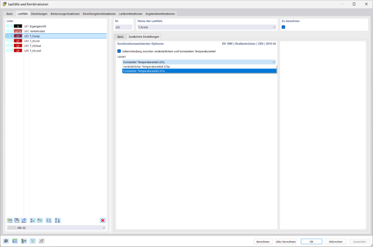
The combination wizard then generates 8 sub-load combinations from these 4 load cases, which are subsequently combined with the other load cases to form load combinations.
- ∆TM,heat + ωN · ΔTN,exp
- ∆TM,cool + ωN · ΔTN,exp
- ∆TM,heat + ωN · ΔTN,con
- ∆TM,cool + ωN · ΔTN,con
- ωM · ∆TM,heat + ΔTN,exp
- ωM · ∆TM,cool + ΔTN,exp
- ωM · ∆TM,heat + ΔTN,con
- ωM · ∆TM,cool + ΔTN,con
Application Example
In this application example, the values specified in the National Annexes are based on the recommended values of the European Committee for Standardization (CEN).
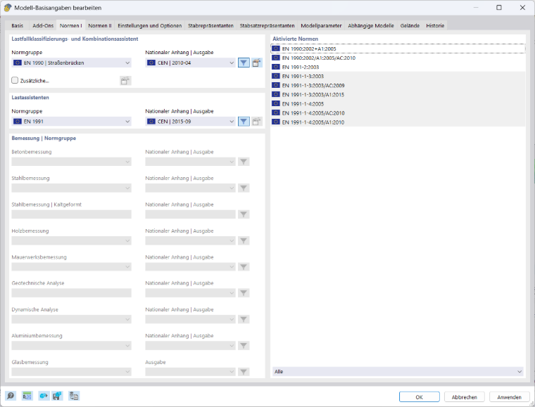
The superstructure consists of a reinforced concrete slab (Type 3). For the characteristic outside air temperatures Tmin and Tmax, the values from DIN EN 1991-1-5 NA, NDP to 6.1.3.2 (1) [2] are used. The maximum and minimum constant temperature components are calculated according to the scheme recommended in Figure 6.1 [1]:
The default value used is T0 = 10°C, as recommended in DIN EN 1991-1-5, Section 6.1.3.3 [1]. This results in the following values for the constant temperature components:
When ∆T < sub> N,con < /sub>, this represents the maximum negative change. Accordingly, it is necessary to apply a constant temperature load of T < sub> c = –26 °C in the model.
The linearly varying component is determined according to Method 1. The recommended values according to EN 1991-1-5, Table 6.1 [2] are used and multiplied by a factor ksur to take into account different covering thicknesses according to EN 1991-1-5, Table 6.2 [2]. For Superstructure Type 3 (concrete structure—plate) without a covering, the variable temperature component for the “Top side warmer than bottom side” load case ∆T M,heat and the variable temperature component for the “Bottom side warmer than top side” load case ∆T M,cool are calculated as follows:
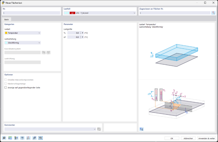
These values, including the top covering thickness factor ksur need to be determined by the user and then applied as a linear temperature load. The vertical temperature distribution for the load case TM,cool should increase linearly from top to bottom. Accordingly, a linear temperature load of ∆T = –8.8 °C shall be applied in the model for this load case.
According to the CEN recommendations in Eurocode 0 [3], the partial safety factor for temperature loads on road bridges is γQ = 1.5, and the combination coefficient is ψ0 = 0.6.
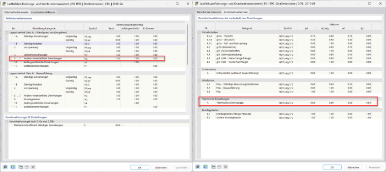
To take into account both constant and variable temperature components simultaneously, the recommended values ωN = 0.35 and ωM = 0.75 according to EN 1991-1-5, Section 6.1.5 [2] apply. The values depend on the National Annex selected for the load wizard (Image 2).
For the temperature components
- ∆TN,con (Tc = –26 °C, ∆T = 0)
- ∆TN,exp (Tc = 27 °C, ∆T = 0)
- ∆TM,heat (Tc = 0, ∆T = 12 °C)
- ∆TM,cool (Tc = 0, ∆T = -8.8°C),
separate load cases are created, and in each load case, a “Temperature” surface load is applied to the superstructure surface. In this application example, the self-weight (Load Case 1) is also taken into account, and a live load (Load Case 2) is applied.
The load cases ∆TN,con and ∆TN,exp are defined as a constant temperature component TN according to Image 1. The load cases ∆TM,heat and ∆TM,cool are defined as a variable temperature component TM according to Image 1.
If the combination wizard is activated, constant and variable temperature components are automatically combined with the other load cases. The values ωN and ωM are incorporated into the scalar factors. Together with the partial safety factor and any combination coefficient, the sub-load combinations described in the previous chapter are then created.
- (ψ0 + γQ,T) · (ωN · ΔTN,exp + ∆TM,heat)
- (ψ0 + γQ,T) · (ΔTN,exp + ωM · ∆TM,heat)
- (ψ0 + γQ,T) · (ωN · ΔTN,exp + ∆TM,cool)
- (ψ0 + γQ,T) · (ΔTN,exp + ωM · ∆TM,cool)
- (ψ0 + γQ,T) · (ωN · ΔTN,con + ∆TM,heat)
- (ψ0 + γQ,T) · (ΔTN,con + ωM · ∆TM,heat)
- (ψ0 + γQ,T) · (ωN · ΔTN,con + ∆TM,cool)
- (ψ0 + γQ,T) · (ΔTN,con + ωM · ∆TM,cool)
with ψ0=0.6; γQ,T=1.5; ωN=0.35 and ωM=0.75
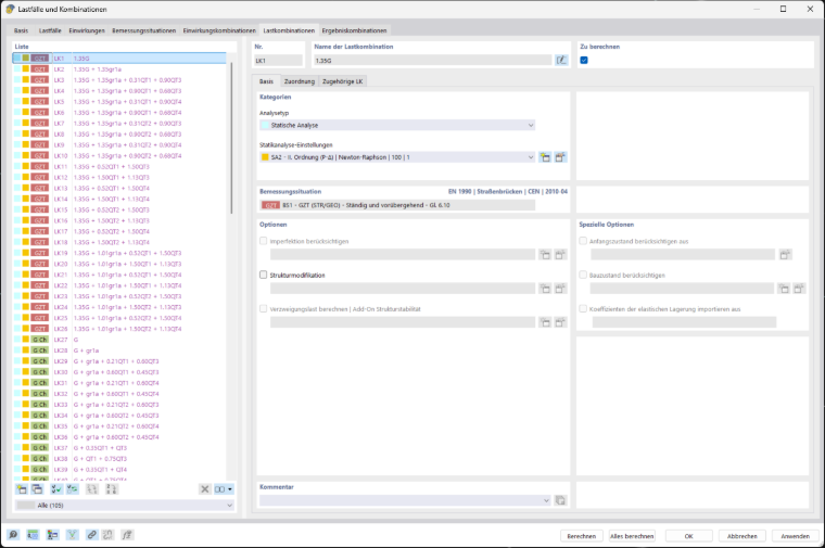
The sub-load combinations are then combined with the other load cases to obtain load combinations (Image 5).
As an example, Load Combination 3 in Figure 5 is modeled in detail:
Constant Temperature Difference Between Different Structural Components
Unfavorable stresses resulting from different constant temperature components between different structural components should also be taken into account. For example, different constant temperature components may arise between light-colored and dark-colored structural components. These stresses shall be applied in addition to the constant temperature components. The values for the different constant temperature components are specified in the National Annex. [1]
Temperature Effects on Bridge Piers
It is necessary to consider the temperature effects on bridge piers if they cause constraint forces or movements in the connected structures. For piers and walls, a linearly varying temperature difference between the outer sides needs to be assumed. The temperature differences are specified in the National Annex. [2]