13 Results
View Results:
Sort by:

In this paper, a novel approach was developed to generate CFD models at the community-level by integrating building information modeling (BIM) and geographical information systems (GIS) to automate the generation of a high-resolution 3-D community model to be employed as an input for a digital wind tunnel using RWIND.

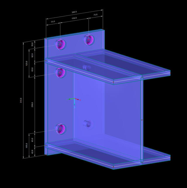
Steel connections in RFEM 6 are defined as an assembly of components. In the new Steel Joints add-on, universally applicable basic components (plates, welds, auxiliary planes) are available for entering complex connection situations. The methods with which connections can be defined are considered in two previous Knowledge Base articles: “A Novel Approach to Designing Steel Joints in RFEM 6" and “Defining Steel Joint Components Using the Library".

You can use the Steel Joints add-on in RFEM 6 to create and analyze steel connections using an FE model. You can control the modeling of the connections via a simple and familiar input of components. Steel joint components can be defined manually, or by using the available templates in the library. The former method is included in a previous Knowledge Base article titled “A Novel Approach to Designing Steel Joints in RFEM 6". This article will focus on the latter method; that is, it will show you how to define steel joint components using the available templates in the program’s library.

One of the innovations in RFEM 6 is the approach to designing steel connections. In contrast to RFEM 5, where the design of steel joints is based on an analytical solution, the Steel Joints add-on in RFEM 6 offers an FE solution for steel connections.
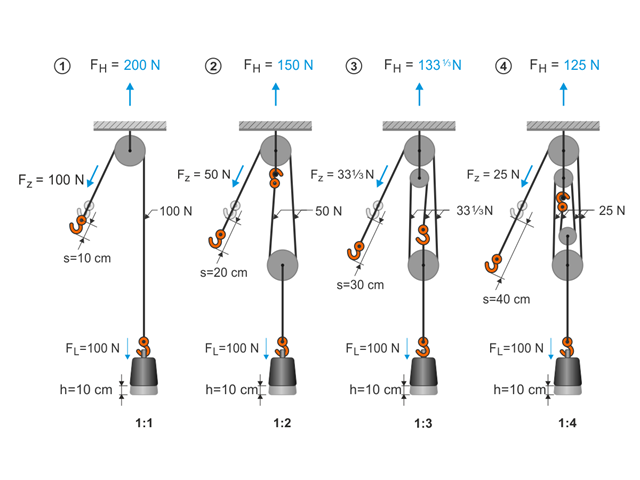
This article describes the basic principles and modeling approaches of pulley systems in RFEM.

Reinforced concrete surface design for slabs, plates, and walls is possible in the RF-CONCRETE Surfaces module according to the ACI 318-19 or the CSA A23.3-19 standard. A common approach for slab design is the use of design strips for determining the average one-way internal forces over the width of the strip. This design strip method essentially takes a two-way slab element and applies a simpler one-way approach to determine the required reinforcement needed along the strip length.
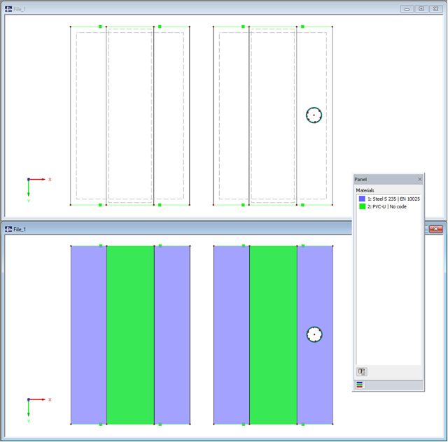
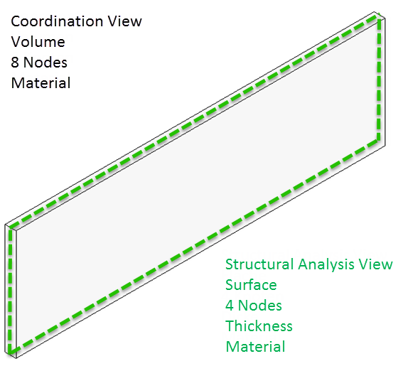
When modeling with finite elements, sooner or later you come up with the question of how two surfaces (2D elements) lying on top of each other can be modeled. Hence, both surfaces are often modeled in the same plane. The possible consequences of this approach, and whether there are better solutions, are described below.
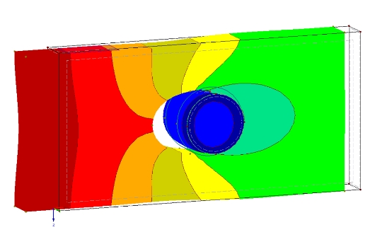
The definition of the non-linear contact problem plays an important role for more detailed investigations of shear/hole bearing connections or their immediate environment. This article uses a solid model to search for comparable and simplified surface models.
Especially if the adjacent area of connection points is to be analyzed, if the geometry and load of the connection do not correspond to the standard specifications, and/or if a model is to be analyzed using an FE model (for example, in plant engineering), the connections must also be evaluated in detail on the FE model.
In the BIM workflow, IFC files are frequently used as the basis for data exchange between CAD and structural engineering software. However, there is a fundamental problem with this approach. This article explains various types of IFC files and provides an overview of the import and export options in Dlubal Software programs.
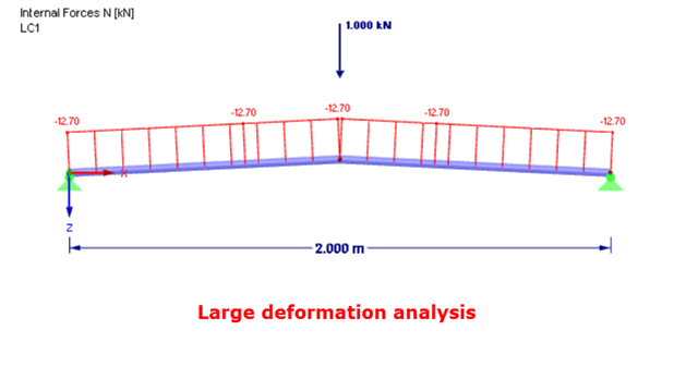
In the case of a post-critical failure, a substantial change occurs in the geometry of a structure. After reaching the instability of the equilibrium, a stable, strength position is reached again. The post-critical analysis requires an experimental approach. It is necessary to manually load the structure in increments, step by step.
![Parameters of Effective Slab Width (Figure 5.3 [1])](/en/webimage/009561/2419376/01-en-png.png?mw=640&hash=c76563b459152b19c98197ea6ba342be89d9a5bc)
In the case of combined FEM structures (surface and member elements) as well as folded plate structures, it is possible to attribute a beam structure for the design on a member to a fictitious T-beam cross-section, whose geometry depends on the effective width. When using the "Rib" member type in RFEM, the stiffness is represented by a slab component (surface element) and a web component (member element). This approach has some design specifics that are explained in this article.

RF‑/FOUNDATION Pro introduced the geotechnical design of single foundations according to EN 1997‑1 in RFEM 5 and RSTAB 8. Depending on the National Annex preset in the add‑on module, you can determine the bearing resistance using Approach 2 or 3 in compliance with EN 1997‑1 up to Version x.04.0108.