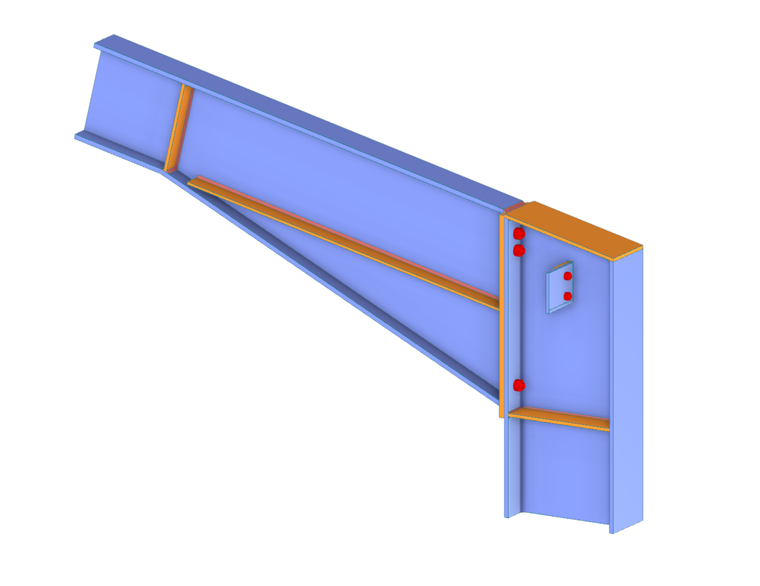
The advantage of the RFEM Steel Joints add-on is that you can analyze steel connections using an FE model for which the modeling runs fully automatically in the background. As a matter of fact, it is controlled by the user via the simple and familiar input of components, as shown in Image 1 and discussed in more detail in the aforementioned articles.
In terms of design, the design checks of the components are carried out on the basis of the loads determined on the FE model. All internal forces are considered in the design (N, Vy, Vz, My, Mz, and Mt); that is, there is no restriction to planar loading. Furthermore, the loading of all load combinations is automatically transferred into the FE model at all selected nodes.
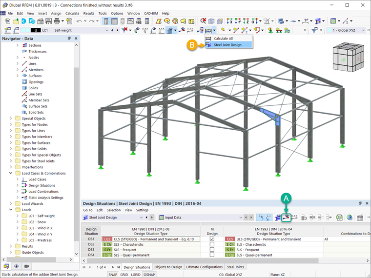
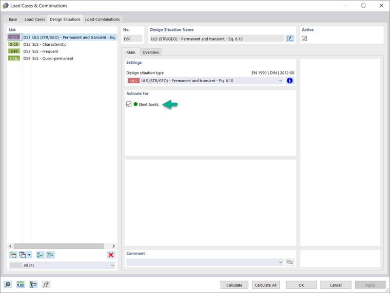
Before assigning the parameters for the design, it is important to activate the design situation of interest for the Steel Joints add-on. Image 2 shows how to activate the ultimate limit state design situation for this add-on.
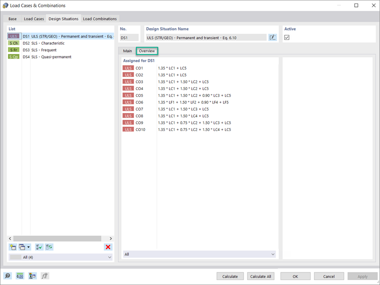
As the image shows, you can do this in the Design Situations tab of the Load Cases & Combinations dialog box. In the Overview tab of the same window, it is possible to display the load combinations assigned for the design situation of interest (Image 3).
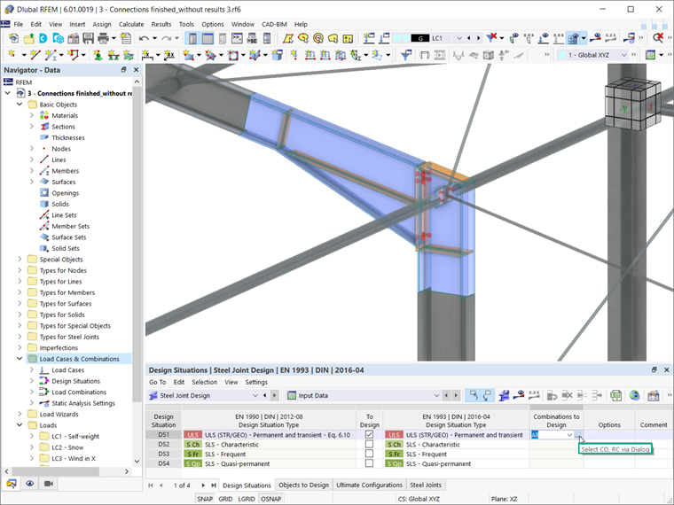
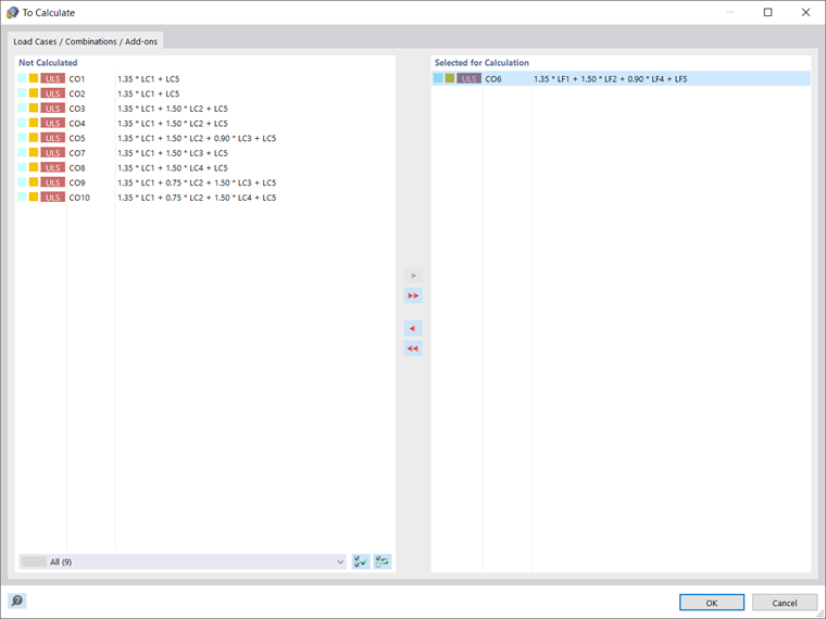
If you want to consider a design situation for a particular load combination (for example, the one with the highest internal forces), you should select the combination of interest in the input data of the Steel Joint Design table, as shown in Images 4 and 5.
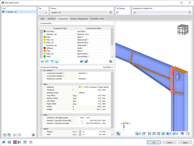
Next, the ultimate design configuration can be defined in the Design Configurations tab of the Steel Joint dialog box, which is accessible via the navigator, the table, or by double-clicking the steel joint itself (in cases when the joint is already available in the RFEM working window). You can create a new configuration, edit an existing one, or select the ultimate configuration from graphics (Image 6).
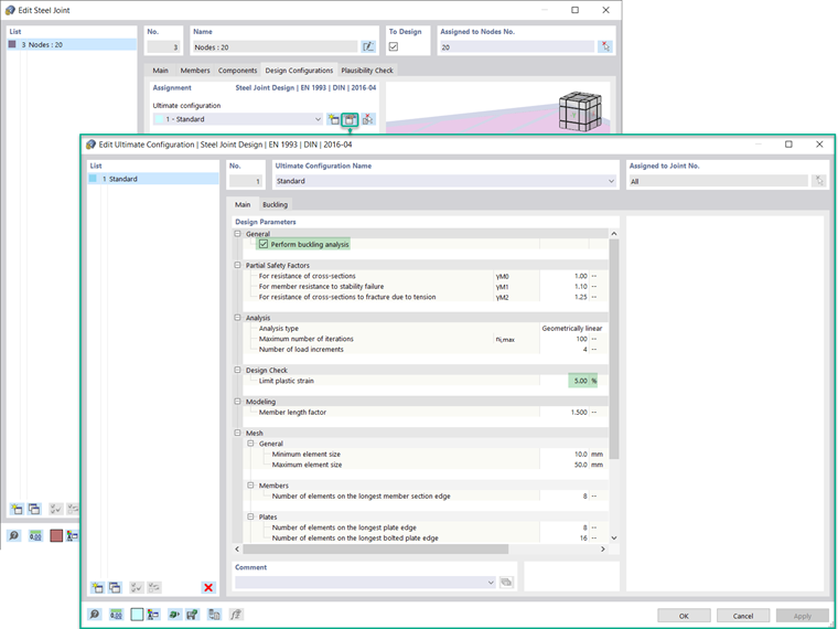
In the Ultimate Configuration dialog box shown in Image 6, it is necessary first to define whether a buckling analysis should be performed. If you activate the check box, the Buckling tab will be available as well. The design parameters such as partial safety factors and limit plastic strain are automatically taken by the standard selected for the add-on in the Base Data of the model, but you can adjust them.
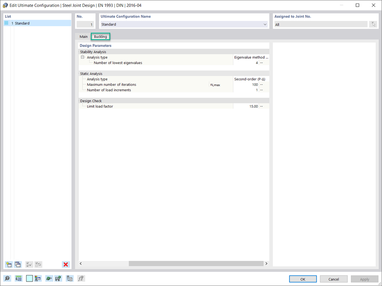
You can also define other design parameters in terms of analysis (that is, the analysis type, number of iterations, and load increments), modeling (that is, the member length factor), and mesh (that is, general parameters such as the element size, as well as specific parameters for the connecting members and joint components).
For the buckling analysis, you can define the lowest number of eigenvalues to be considered, as shown in Image 7. The limit load factor for the design check is set to 15 according to Eurocode 3 [[#Refer [1]]], but you can redefine it.
Once the steel connection and the associated design parameters are defined, you can run the calculation by clicking the “Show results” button in the Steel Joints table, or via “Steel Joint Design” in the toolbar, as shown in Image 8. The evaluation of results and their documentation will be discussed in an upcoming Knowledge Base article.