20 Results
View Results:
Sort by:

Wind direction plays a crucial role in shaping the outcomes of Computational Fluid Dynamics (CFD) simulations and the structural design of buildings and infrastructures. It is a determining factor in assessing how wind forces interact with structures, influencing the distribution of wind pressures, and consequently, the structural responses. Understanding the impact of wind direction is essential for developing designs that can withstand varying wind forces, ensuring the safety and durability of structures. Simplified, the wind direction helps in fine-tuning CFD simulations and guiding structural design principles for optimal performance and resilience against wind-induced effects.

The “Modal Analysis” add-on in RFEM 6 allows you to perform modal analysis of structural systems, thus determining natural vibration values such as natural frequencies, mode shapes, modal masses, and effective modal mass factors. These results can be used for vibration design, as well as for further dynamic analyses (for example, loading by a response spectrum).

Modal analysis is the starting point for the dynamic analysis of structural systems. You can use it to determine natural vibration values such as natural frequencies, mode shapes, modal masses, and effective modal mass factors. This outcome can be used for vibration design, and it can be used for further dynamic analyses (for example, loading by a response spectrum).

Steel connections in RFEM 6 are defined as an assembly of components. In the new Steel Joints add-on, universally applicable basic components (plates, welds, auxiliary planes) are available for entering complex connection situations. The methods with which connections can be defined are considered in two previous Knowledge Base articles: “A Novel Approach to Designing Steel Joints in RFEM 6" and “Defining Steel Joint Components Using the Library".

The design of cross-sections according to Eurocode 3 is based on the classification of the cross-section to be designed in terms of classes determined by the standard. The classification of cross-sections is important, since it determines the limits of resistance and rotation capacity due to local buckling of cross-section parts.

Complex structures are assemblies of structural elements with various properties. However, certain elements can have the same properties in terms of supports, nonlinearities, end modifications, hinges, and so on, as well as design (for example, effective lengths, design supports, reinforcement, service classes, section reductions, and so on). In RFEM 6, these elements can be grouped on the basis of their shared properties and thus can be considered together for both modeling and design.

Concrete on its own is characterized by its compressive strength. An important part of reinforced concrete is reinforcing steel, which contributes to both the compressive and the tension resistance of the concrete. Welded wire fabric is generally located in the tension areas of the beams or surface elements (hollow core ceiling, wall, shell) to transfer the tensile forces induced by external loading.

The classification of cross-sections is intended to determine the limits of resistance and rotational capacity due to local buckling of cross-section parts. In EN 1999‑1‑1, 6.1.4.2 (1), four classes are defined.

Table 3.1 of EN 1993‑1‑8:2010‑12 defines the nominal values of the yield strength and the ultimate limit strength of bolts. The bolt classes given here are 4.6, 4.8, 5.6, 5.8, 6.8, 8.8, 10.9. The note for this table states that the National Annex may exclude certain bolt classes. For the NA of Germany, these are the bolt classes 4.8, 5.8, and 6.8.

In order to consider inaccuracies regarding the position of masses in a response spectrum analysis, standards for seismic design specify rules that have to be applied in both the simplified and multi-modal response spectrum analyses. These rules describe the following general procedure: The story mass must be shifted by a certain eccentricity, which results in a torsional moment.

When designing a steel cross-section according to Eurocode 3, it is important to assign the cross-section to one of the four cross-section classes. Classes 1 and 2 allow for a plastic design; classes 3 and 4 are only for elastic design. In addition to the resistance of the cross-section, the structural component's sufficient stability has to be analyzed.
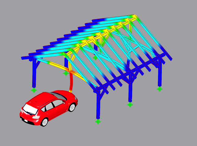
The fundamental requirements of a structural system are (according to the basis of structural design) sufficient ultimate limit state, serviceability, and resistance. Structures must be designed in such a way that no damage occurs due to events such as the impact of a vehicle.

Fin plate connections are a popular form of pinned steel connection and are commonly used for secondary beams in steel structures. They can be used easily in beam structures arranged on the top edge (for example, working platforms). Manufacturing expenditures in the workshop as well as the onsite assembly costs are normally manageable. The design seems to be completed easily and quickly, but it has to be put into perspective to a certain extent in the following text. Moreover, this connection type is basically possible as a pinned beam-to-beam or pinned beam-to-column connection; the former case is the more common one in design practice.

Wind is the only climatic load acting on every type of structure in every country in the world, unlike snow. The wind speed depends on the geographic location of the building. Currently, this is one of the main reasons for the necessity of regional division (wind zone) and consideration of the altitude stipulated within the official standards; the variation of the dynamic pressures according to the height above the ground for a "normal" site deprived of masking effect should be taken into account as well.

Prior to the analysis of steel cross‑sections, the cross‑sections are classified according to EN 1993‑1‑1, Sec. 5.5, with respect to their resistance and rotation capacity. Thus, the individual cross-section parts are analyzed and assigned to Classes 1 to 4. The cross-section classes are determined subsequently and usually assigned to the highest class of the cross-section parts. If plastic resistance is to be applied to further design of cross-sections of Class 1 and Class 2, you can analyze the elastic resistance of cross-sections as of Class 3. In the case of cross-sections of Class 4, local buckling occurs even before reaching the elastic moment. In order to take this effect into account, you can use effective widths. This article describes the calculation of the effective cross-section properties in more detail.
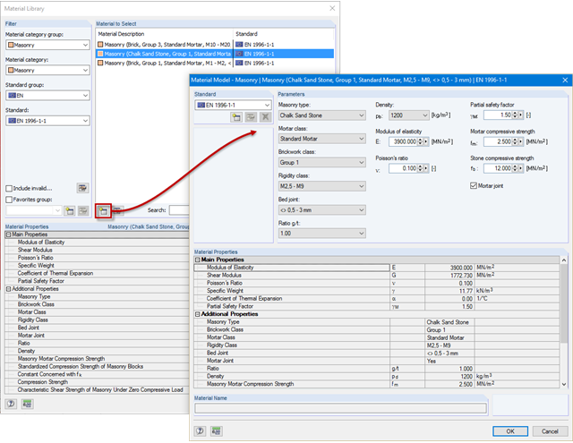
In order to estimate the structural behavior of masonry close to reality by using RFEM, it is necessary to select a material and a material model first. Since masonry responds to tension by cracking, you have to select a nonlinear material model. This can be selected if the RF-MAT NL add-on module is available.
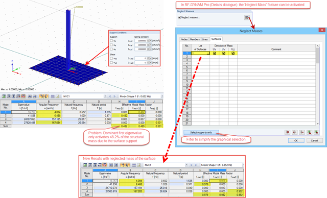
As of the version 5.06.1103, masses of nodes, lines, members, and surfaces can be neglected in RF‑DYNAM Pro. The setting to activate this feature can be found in the Details dialog box; the neglected masses are valid for all defined mass cases.
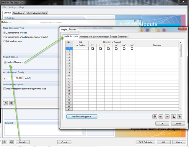
In the DYNAM Pro add‑on module for RSTAB, you can now neglect masses that may have a negative effect on the equivalent mass factor when calculating eigenvalues. To do this, you can disable the masses under [Details]. These include primarily mass points located in the support of the structures.
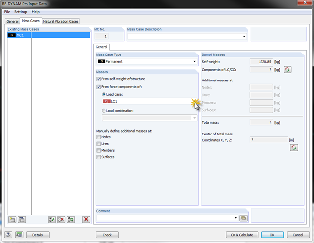
In RF-/DYNAM Pro - Natural Vibrations, it is possible to transfer complete load cases/load combinations as masses. To do this, you can simply save the load case or the load combination to be considered as a mass case in the add‑on module.

The new RF‑/DYNAM Pro - Natural Vibrations module has been available since RFEM version 5.04.xx and RSTAB version 8.04.xx were released. Masses can now be imported directly from load cases and load combinations.