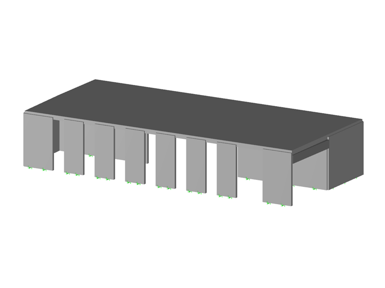
Common in construction and civil engineering structures, reinforced or reinforced concrete is used, among other things, in slabs, walls, shells, columns, beams, ribs, or even foundations.
Nowadays, the execution time of construction works and commissioning of goods is very short. The best solution for a time gain is the use of ready-to-install reinforcement - welded mesh.
What is a welded mesh and how to use it in RFEM?
A welded mesh is a concrete reinforcement made up of crossed steel bars assembled by welding. Each welded mesh is characterized by the dimensions of the panel or roll (length, width, area), the dimensions of its mesh (length and width), the diameter of its fibers, as well as their steel section (in cm2/m), nominal mass, and the number of fibers per panel. RFEM, the software for calculating and designing concrete structures, integrates several ranges of welded meshes in the library of its additional module RF-CONCRETE Surfaces. It quickly enables the definition of planned or additional reinforcement areas through easy selection of meshes classified by country, product range, and designation. Conventional welded meshes from a few countries are accessible by default, such as the meshes from Germany, Austria, Netherlands, USA,... In France, ADETS welded mesh ranges are widely used.
What welded meshes are offered by ADETS?
ADETS (Technical Association for the Development for the Employment of Welded Mesh) distinguishes two types of welded meshes:
- Structural welded meshes designated by the letters "ST" (structural mesh). They contribute to the structural resistance within the structure and comply with the standard NF A 35-080-2.
- Surface welded meshes designated "PAF" (anti-crack panel) or "RAF" (anti-crack roll): these are very light meshes that play no structural role within the structure. They are reinforcements that help to limit surface cracking and prevent significant failure in case of cracking (anti-shattering role). They meet the requirements of the standard NF A 35-024 when the steel grade is B600A or the standard NF A 35-080-2 for grade B500A.
Which mesh to choose for your projects?
The choice of welded mesh is made based on the type of structure and the loads acting on the structure. Some professional recommendations indicate the minimum types of welded meshes to be installed. These are for example, DTU 13.3.3 for individual house floors, DTU 13.3.1 for industrial floors, DTU 23.5 for beam and hollow pot floors, DTU 26.2 for non-structural poured or floating slabs.
The following table presents the minimum recommended welded meshes based on use, application domain in compliance with the prescriptions of the European Concrete Design Standards (Eurocode 2 and Eurocode 8).
| Use | Products | Application | Welded Mesh Grade |
|---|---|---|---|
| Individual House Floors | - | ST 25 CS / ST 25 C | B500A (if secondary seismic element) or B500B (if primary seismic element) |
| Industrial or Similar Use Floors | ST 15 C | Unreinforced floor thickness 15 to 23 cm | B500A (if secondary seismic element) or B500B (if primary seismic element) |
| -//- | All structural meshes (ST) | Unreinforced floor thickness > 23 cm and reinforced floor | B500A (if secondary seismic element) or B500B (if primary seismic element) |
| Non-Industrial or Similar Use Floors | PAF 10 / PAF C | Unreinforced floor | B500A |
| -//- | ST 50 C | Minimum percentage reinforced floor | B500A (if secondary seismic element) or B500B (if primary seismic element) |
| -//- | All structural meshes (ST) | Reinforced floor | - |
| Wall / Cast Concrete Walls | PAF V / PAF 10 | Face reinforcement of outer walls | B500A |
| Beam Hollow Block Floors (compression slabs) | PAF 10 | Seismic | B500A |
| -//- | PAF C / PAF R | According to the spacing of the beams | B500A |
| Concrete Tanks |
|
According to the thickness of walls D and d ≥ 8 mm | B500B |
| Other Applications | All structural meshes (ST) | - | B500A (if secondary seismic element) or B500B (if primary seismic element) |
Any design of reinforced concrete structures must be carried out by a Structural Engineer, Calculator, or Professional following normative calculation methods manually or on calculation software like RFEM.
How to use ADETS meshes in RFEM software?
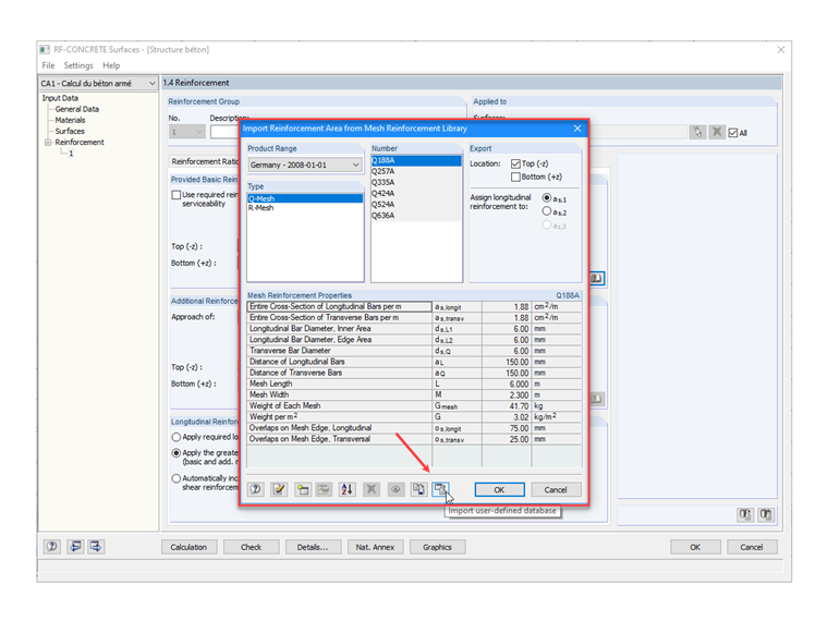
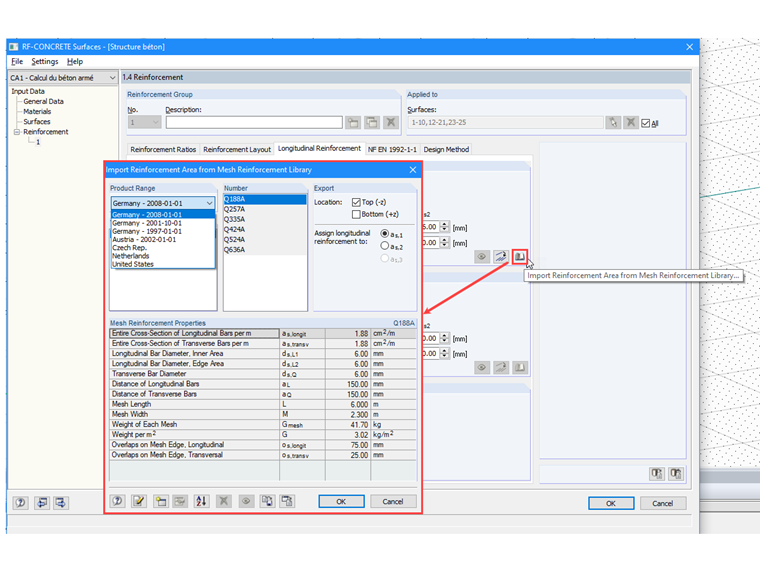
ADETS meshes are not available in the library; therefore, they need to be created. Tools in the Import Reinforcement Area from the Mesh Library dialog facilitate the creation or import of new welded mesh ranges. You can use ADETS product ranges prepared in the .db3 file and downloadable at the bottom of this technical article for your study projects.
How to import a mesh database from the .db3 file?
At the bottom of the Import Reinforcement Area from the Mesh Library dialog, click on the Import User-Defined Database button. Then, close the dialog by clicking [OK] to confirm the addition. Upon reopening this dialog, the new welded meshes will be accessible.