9 Results
View Results:
Sort by:

The optimal scenario in which punching shear design according to ACI 318-19 [1] or CSA A23.3:19 [2] should be utilized is when a slab is experiencing a high concentration of loading or reaction forces occurring at one single node. In RFEM 6, the node in which punching shear is an issue is referred to as a punching shear node. The causes of these high concentration of forces can be introduced by a column, concentrated force, or nodal support. Connecting walls can also cause these concentrated loads at wall ends, corners, and ends of line loads and supports.
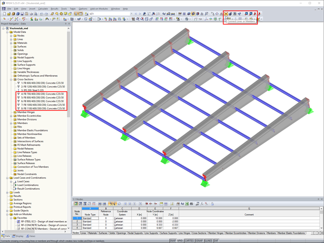
In RFEM, if you want to insert a tapered member with intermediate nodes into an existing model, the issue often arises how to determine the individual cross-section depths of the tapered members quickly. The "Connect Lines or Members" command comes in handy for this purpose.

In EN 1993-1-1, the General Method was introduced as a design format for stability analyses that can be applied to planar systems with arbitrary boundary conditions and variable structural height. The design checks can be performed for loading in the main load-bearing plane and simultaneous compression. The stability cases of lateral-torsional buckling and flexural buckling are analyzed from the main supporting plane; that is, about the weak component axis. Therefore, the issue often arises as to how to design, in this context, flexural buckling in the main load-bearing plane.
.png?mw=640&hash=bfebd5ea2d4f77a817fa987424a23a799b3fe711)
When you perform the subsequent modeling of a beam under an existing floor, the first issues that arise are which forces should be transferred between the downstand beam and the floor, and whether a composite effect is the goal. In this case, the floor should rest on the downstand beam without a composite.

Slender bending beams that have a large h/w ratio and are loaded parallel to the minor axis tend to have stability issues. This is due to the deflection of the compression chord.

When modeling a reinforced concrete rib with a masonry wall above, there is the risk that the rib is underdesigned if the structural behavior of the masonry is not correctly considered and the connection between the masonry wall and downstand beam is not modeled sufficiently accurately. This article deals with this issue and shows the possible modeling options of such a structure. In this example, the reinforcement is determined only from the internal forces and without secondary minimum reinforcement.

When introducing and transferring horizontal loads such as wind or seismic loads, increasing difficulties arise in 3D models. To avoid such issues, some standards (for example, ASCE 7, NBC) require the simplification of the model using diaphragms that distribute the horizontal loads to structural components transferring loads, but cannot transfer bending themselves (called "Diaphragm").

Shell buckling is considered to be the most recent and least explored stability issue of structural engineering. This is due less to a lack of research activities than to the complexity of the theory. With the introduction and further development of the finite element method in structural engineering practice, some engineers no longer have to deal with the complicated theory of shell buckling. Evidence of the problems and errors to which this gives rise is very well summarized in [1].

Basically, you can design the structural components made of cross-laminated timber in the RF-LAMINATE add-on module. Since the design is a pure elastic stress analysis, it is necessary to additionally consider the stability issues (flexural buckling and lateral-torsional buckling).