


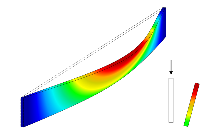
The beam has a lateral displacement with simultaneous rotation (see Image 01). This is called flexural-torsional buckling or lateral buckling. Similar to flexural buckling, where a member buckles suddenly when the Euler load is reached, the compression chord shifts from a critical lateral buckling load during flexural-torsional buckling. This results in a critical bending moment Mcrit, which results in a critical stress for lateral buckling σcrit.
Symbols used:
| L | Beam length |
| E | Modulus of elasticity |
| G | Shear modulus |
| Iz | Second moment of area about the weak axis |
| IT | Torsion moment of inertia |
| Iω | Warping resistance |
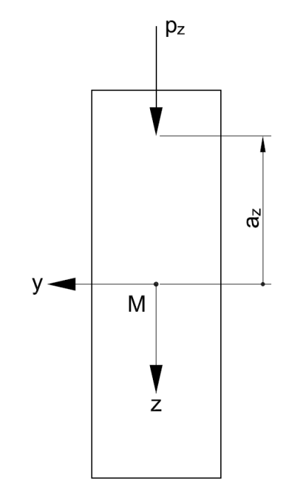
| az | Distance of the load application from the shear center |
| e | Distance of the member elastic foundation from the shear center |
| KG | Elastic rotational spring on support in Nmm |
| KΘ | Elastic rotational restraint in N |
| Ky | Elastic member foundation in N/mm² |
Analytical Determination of Mcrit
To determine the bending moment where a beam becomes unstable, the engineer can use analytical solutions from the literature, but these are limited in their application. In [1], the following equation is derived for a single-span beam with lateral and torsional restraints and hinged at both sides, with a constant bending moment and load application at the shear center.
In the case of cross-sections not free to warp (for example, a narrow rectangular cross-section in timber construction), the warping stiffness can be set to zero; thus, the part in the parentheses is omitted.
Correction Factors
Since there are many more cases in structural analysis than those mentioned above, correction factors have been introduced in order to take into account, for example, deviating moment distributions, support situations, and a different load application. For this, the length of the beam is modified with the factors and results in an effective length lef. This is described in [2], among others, as follows.
az is the distance of the load application from the shear center.
If the load acts on the bottom side of the beam, you have to consider az with negative signs. The coefficients a1 and a2 are shown in Image 03.
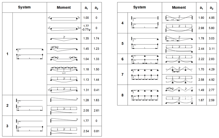
The different systems have to be understood as follows:
- Single-span beam with lateral and torsional restraints and hinged at both sides
- Restrained beam
- Cantilever with lateral and torsional restraint at the free end
- Beam fixed on both sides
- Single-span beam with restraint on one side
- Two-span beam
- Continuous beam with lateral and torsional restraint – inner span
- Continuous beam with lateral and torsional restraint – outer span
Mcrit in Standards
The standards suggest the lateral buckling design according to the equivalent member method. You have to calculate the critical moment with the 5% quantile values of the stiffnesses. Thus, the following results for timber structures:
The critical bending stress results in:
Elastic Supports
If you want to consider an elastic rotational spring (for example, resulting from the flexibility of the lateral and torsional restraint) on the support, an elastic rotational restraint (for example, from trapezoidal sheeting), or an elastic member elastic foundation (for example, from bracings), you can extend the previous equation as follows [2].
where
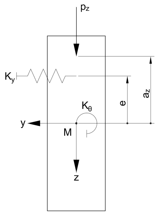
If the rotational spring KG on the support is considered as infinitely rigid, α = 1. The elastic rotational restraint KΘ is usually not taken into account in timber structures, as no studies are available here. Thus, the parameter KΘ is included in the equation with the value 0. The elastic member elastic foundation Ky, resulting from a bracing or a shear panel, has a favorable effect on the lateral buckling behavior of a beam.
Finding the solution for such eigenvalue issues in a skillful way will be described with different examples in the next article.