19 Results
View Results:
Sort by:

In this article, a lap joint of a ZL purlin on a monopitch roof is modeled and designed using the Steel Joints add-on, and compared with the load-bearing capacity table of the manufacturer.

As you may already know, RFEM 6 offers you the possibility to consider material nonlinearities. This article explains how to determine internal forces in slabs modeled with nonlinear material.

In computational fluid dynamics (CFD), complex surfaces that are not completely solid can be modeled using porous or permeability media. In the actual world, examples of such things include windbreak fabric structures, wire meshes, perforated facades and claddings, louvers, tube banks (stacks of horizontal cylinders), and so on.

You can model and analyze masonry structures in RFEM 6 with the Masonry Design add-on that employs the finite element method for the design. Complex masonry structures can be modeled, and static and dynamic analysis can be performed, given that a nonlinear material model is implemented in the program to display the load-bearing behavior of masonry and the different failure mechanisms. You can enter and model masonry structures directly in RFEM 6 and combine the masonry material model with all common RFEM add-ons. In other words, you can design entire building models in connection with masonry.

This article describes how a flat slab of a residential building is modeled in RFEM 6 and designed according to Eurocode 2. The plate is 24 cm thick and is supported by 45/45/300 cm columns at distances of 6.75 m in both the X and Y directions (Image 1). The columns are modeled as elastic nodal supports by determining the spring stiffness based on the boundary conditions (Image 2). C35/45 concrete and B 500 S (A) reinforcing steel are selected as the materials for the design.
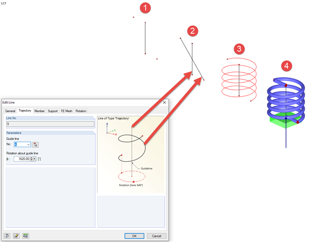
In RFEM, you can create screw lines using the "Trajectory" type line. To do this, you need a center line/guide line around which the line can be modeled, as well as a start and end point. Then, you can create a "Trajectory" type line between the start and end points; this initially appears as a straight line.

When modeling structural bearing systems, especially hall structures, some substructures of a foundation with no influence on the rising structure are not modeled in RFEM/RSTAB. In the case of hall structures, these are, for example, reinforced concrete floor slabs, strip foundations, and the ties between column foundations.
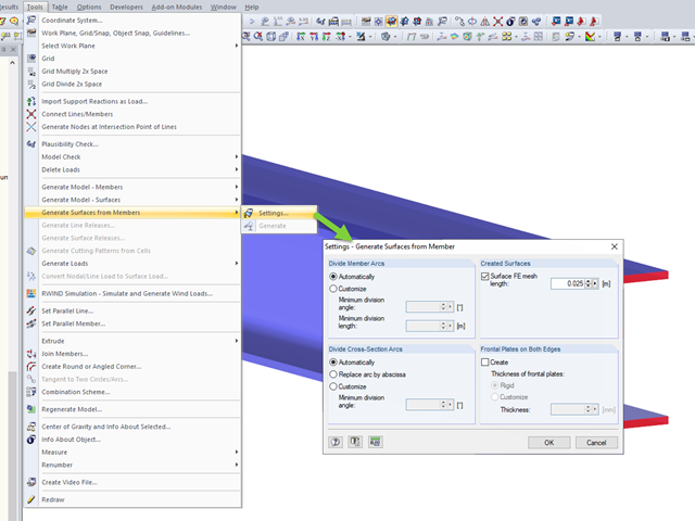
RFEM allows you to automatically generate surfaces from modeled members. This has the advantage that, for example, the surface thicknesses of a steel section are generated automatically.
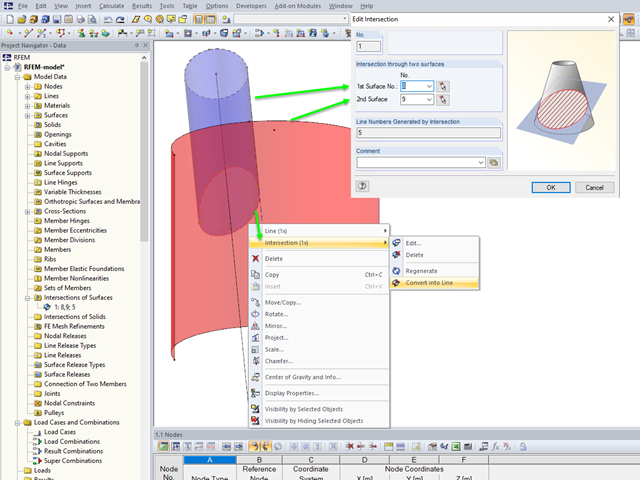
If you want to model two intersecting surfaces, RFEM offers you the possibility to create the section line automatically. In the program, this function is referred to as intersection. When generating an intersection, the modeled surface is split into components. This has the advantage that the components can be taken into account in the determination of the internal forces, or deactivated.

For cross‑laminated structures with large spans, downstand beams or hybrid structures are often used. They can be modeled in RFEM 5 by using surfaces and member cross‑sections. In both structural systems, curved downstand beams are also possible without any problems. In the case of the curved surface, the member is always appropriately generated by means of the automatic member eccentricity with the thickness distance of the surface and the member. The downstand beam can also be connected flexibly by means of a line release.
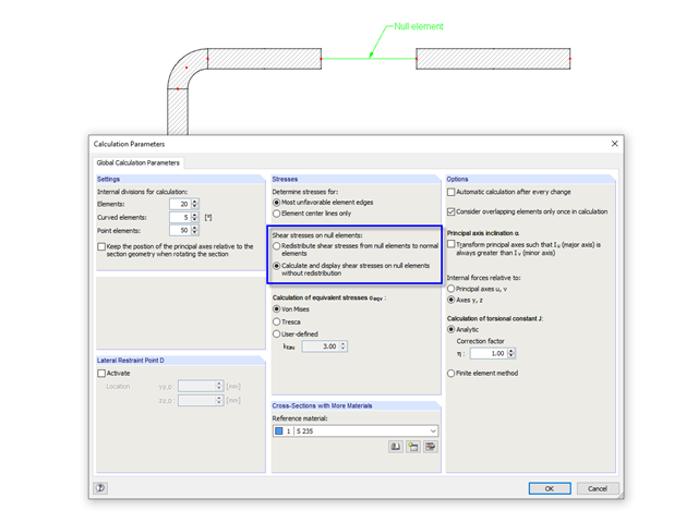
In cross‑sections created in SHAPE‑THIN, the openings, such as bolt holes, can be modeled by using the elements with zero thickness. The program provides two options for calculating shear stresses in the area of such null elements.

When modeling a reinforced concrete rib with a masonry wall above, there is the risk that the rib is underdesigned if the structural behavior of the masonry is not correctly considered and the connection between the masonry wall and downstand beam is not modeled sufficiently accurately. This article deals with this issue and shows the possible modeling options of such a structure. In this example, the reinforcement is determined only from the internal forces and without secondary minimum reinforcement.
When modeling with finite elements, sooner or later you come up with the question of how two surfaces (2D elements) lying on top of each other can be modeled. Hence, both surfaces are often modeled in the same plane. The possible consequences of this approach, and whether there are better solutions, are described below.
In RFEM, structures can be modeled and analyzed in a spatial environment. The permanent 3D visualization helps you to better understand complex models and to represent the force flux. However, you can switch from a spatial mode to a planar sheet mode in the documentation of a calculation. To do this, you have to describe the spatial calculation of the structure with all the necessary properties on "flat" paper pages for an independent reader. Usually, you try to display the load actions and the corresponding results by using an orthogonal view of the substructure of the entire structure. Obviously, the load symbols depicted in the 3D mode in a view perpendicular to the load become unrecognizable due the missing expansion. In order to still be able to create a clear representation of all information, the corresponding adjustments are available in RFEM.

The following article describes the design of a single-span beam subjected to bending and compression, which is performed according to EN 1993‑1‑1 in the RF-/STEEL EC3 add-on module. Since the beam is modeled with a tapered cross-section and thus it is not a uniform structural component, the design must be performed either according to General Method in compliance with Sect. 6.3.4 of EN 1993‑1‑1, or according to the second-order analysis. Both options will be explained and compared, and for the calculation according to the second-order analysis, there is an additional design format using Partial Internal Forces Method (PIFM) available. Therefore, the design is divided into three steps: design according to Sect. 6.3.4 of EN 1993‑1‑1 (General Method), design according to the second‑order analysis, elastic (warping torsion analysis), design according to the second‑order analysis, plastic (warping torsion analysis and Partial Internal Forces Method).
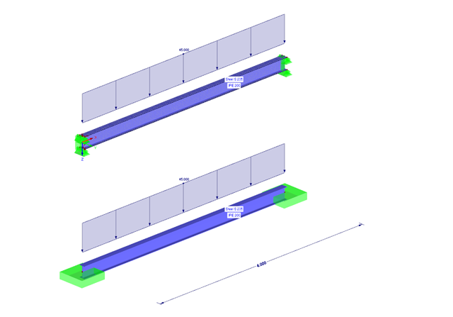
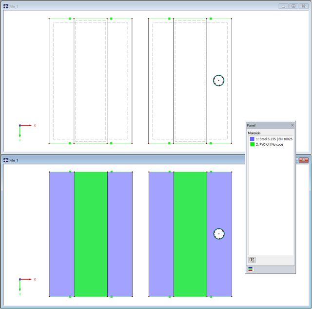
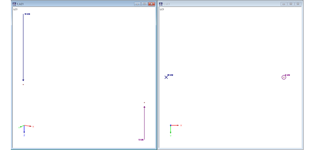
The following example presents a comparison between a shell model and a simple member model performed in RFEM. In the case of the shell model, there is a beam suspended in surfaces, which is modeled with restraints on both sides due to the boundary conditions. This is a statically indeterminate system that forms plastic hinges when overloaded. The comparison is carried out on a member model that has the same boundary conditions as the shell model.
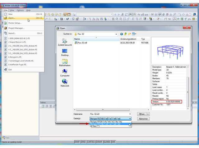
In RFEM, you can open and further edit structures with loads and load cases that have been modeled in RSTAB. For example, this may be necessary if you realize during the model input that it is useful to include surface elements such as wall surfaces and others in the existing RSTAB model.
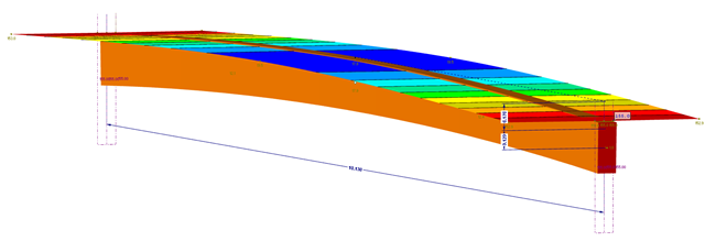
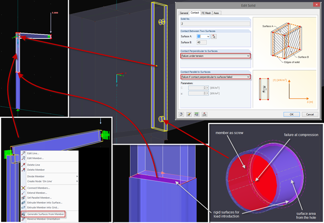
This part explains the determination of forces arising when screwing a straight cross-laminated timber plate to a curved glulam beam. For this, a glulam beam with a curved member was modeled in RFEM. The member has a precamber of 12 cm, since the preliminary design showed that the applied precamber of 6 cm will never be sufficient to maintain l/300. The dimensions of the bottom chord are 12 cm wide by 32 cm high. The plate was selected in RF‑LAMINATE as a three‑layer plate with a thickness of 8 cm.
Sometimes, a detailed examination is needed of problematic areas of a joint or the stiffness of a frame joint. The following tips can help you with this. As an example, a frame joint was modeled using RF‑FRAME‑JOINT Pro and members, and used as a basis.