18 Results
View Results:
Sort by:

When it comes to wind loads on building type structures as per ASCE 7, numerous resources can be found to supplement design standards and aid engineers with this lateral load application. However, engineers may find it more difficult to find similar resources for wind loading on non-building type structures. This article will examine the steps to calculate and apply wind loads as per ASCE 7-22 on a circular reinforced concrete tank with a dome roof.
RWIND 2 is a program for generating wind loads based on CFD (Computational Fluid Dynamics). The wind flow numerical simulation is generated around any building, including irregular or unique geometry types, to determine the wind loads on surfaces and members. RWIND 2 can be integrated with RFEM/RSTAB for the structural analysis and design or as a stand-alone application.

RFEM and RSTAB programs provide parameterized input as an advantageous product feature to create or adjust models by means of variables. This article will show you how to define global parameters and use them in formulas to determine numerical values.

RWIND 2 is a program for generating wind loads based on CFD (Computational Fluid Dynamics). The wind flow numerical simulation is generated around any building, including irregular or unique geometry types, to determine the wind loads on surfaces and members. RWIND 2 can be integrated with RFEM/RSTAB for the structural analysis and design or as a stand-alone application.

The add-on modules for designing structural member components according to national, European, and international standards also show design results in addition to numerical output in tables graphically, as diagrams displayed on the framework.

The "4.0 Results - Summary" table displays the infinity norm at the end of the load case results. The norm is used to estimate the largest eigenvalue of a structure. The largest eigenvalue of a structure is estimated by numerical analysis, as accurate determination can be very time-consuming.
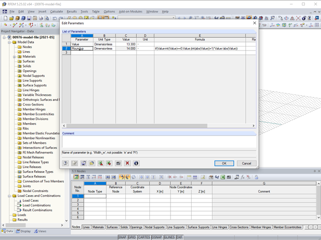
In RFEM, RSTAB, and SHAPE-THIN, you can use formulas to determine a numerical value.
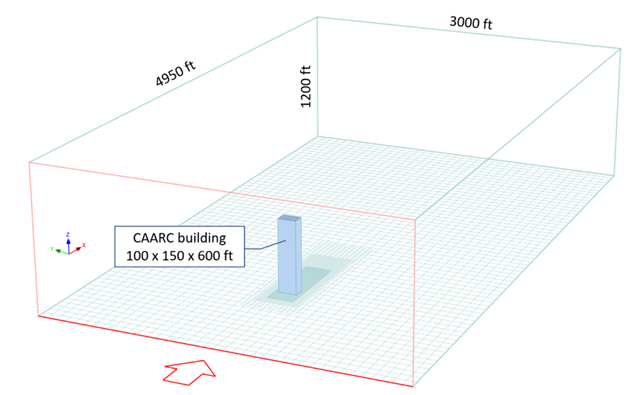
The following study compares the wind pressure on a tall building obtained by RWIND Simulation with the results published by Dagnew et al. at the 11th Americas Conference on Wind Engineering in June, 2009. In this paper, the Commonwealth Advisory Aeronautical Council (CAARC) building is used as a model, and the results of several different numerical methods are compared with experimental data obtained from wind tunnels.
Numerous nonlinearities can occur in a structural system. The RF-DYNAM Pro - Nonlinear Time History add-on module was developed in order to model them realistically in a dynamic analysis. To explain how the add-on module works, the procedure is described below with an example.

When it comes to wind loads on building type structures as per ASCE 7, numerous resources can be found to supplement design standards and aid engineers with this lateral load application. However, engineers may find it more difficult to find similar resources for wind loading on non-building type structures. This article will examine the steps to calculate and apply wind loads as per ASCE 7-16 on a circular reinforced concrete tank with a dome roof.
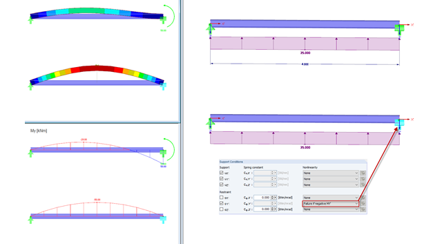
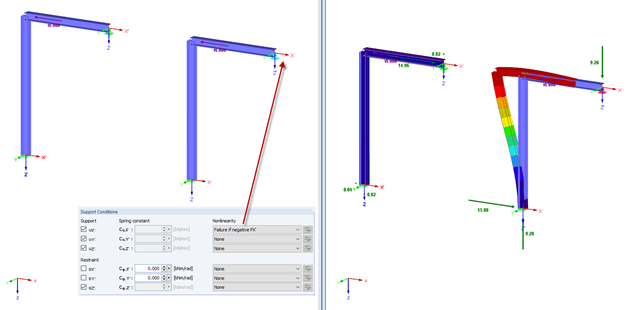
In practice, an engineer often faces the task of representing the support conditions as close to the reality as possible in order to be able to analyze the deformations and internal forces of the structure subjected to their influence and to enable construction that is as cost efficient as possible. RFEM and RSTAB provide numerous options for defining nonlinear nodal supports. This second part describes the options for creating a nonlinear support for a restraint and provides a simple example. For a better understanding, the result is always compared to a linearly defined support.
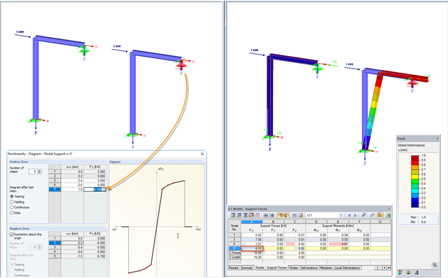
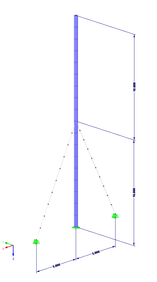
RFEM and RSTAB provide numerous options for nonlinear definitions of nodal supports. With regard to an earlier article, further possibilities of the nonlinear support design for a movable support are shown in a simple example in this article. For a better understanding, the result is always compared to a linearly defined support.
In practice, an engineer often faces the task of representing the support conditions as close to the reality as possible in order to be able to analyze the deformations and internal forces of the structure subjected to their influence, and to enable construction that is as cost-effective as possible. RFEM and RSTAB provide numerous options for defining nonlinear nodal supports. The first section of my article describes the options for creating a nonlinear free support and provides a simple example. For a better understanding, the result is always compared to a linearly defined support.
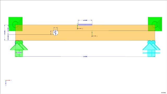
This article presents a bending beam with a circular opening analyzed using the numerical method. As a reference point, there is an example of a perforated beam from [1]. In our case, the 3D model was simplified to a two-dimensional discretization.
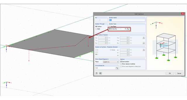
If a section is not on a straight line but on a curved or angled line, this line has to be defined accordingly as a polyline or a curved line. You can define the section along a line using the "Create Section Numerically" function.

RFEM and RSTAB provide numerous interfaces with other programs for data exchange. In the respective programs, different names are often used for the same materials and cross-sections. Therefore, it is necessary to convert the material and cross‑section names in order for them to be recognized by the program after the data exchange.
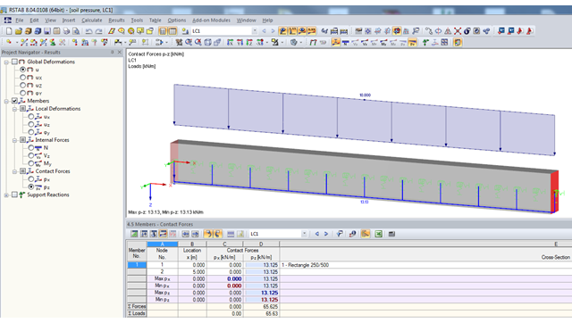
If a model should contain members with elastic foundations, the contact forces and moments are displayed in numerical form in the result windows. The graphical display of results is specified by the "Members" entry in the Results Navigator.
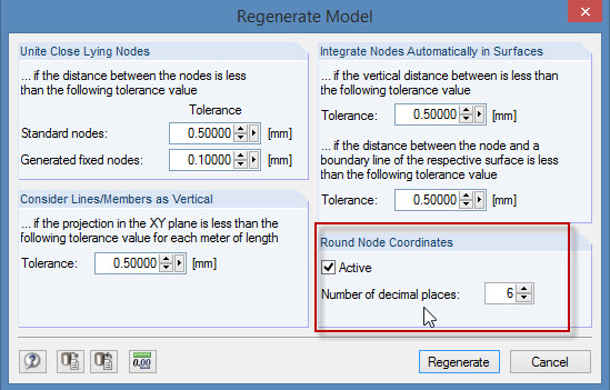
During the cooperation between the structural and design engineers, the DXF format is often used if there is no direct interface. However, the geometrical data of these DXF files are not always accurate. For example, an inaccuracy in the third decimal place is not noticeable, but it can lead to numerical problems when generating the FE mesh in RFEM.