10 Results
View Results:
Sort by:

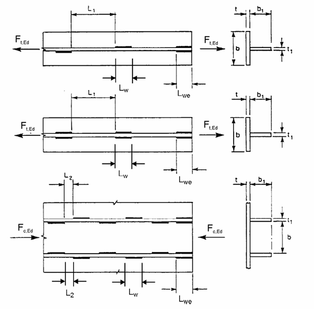
In CRANEWAY, the action of a rail as "statically effective" or "statically ineffective" is defined under "Rail‑Flange Connection" in the Details dialog box. This setting controls the calculation of the load introduction length according to EN 1993-6, Tab. 5.1.
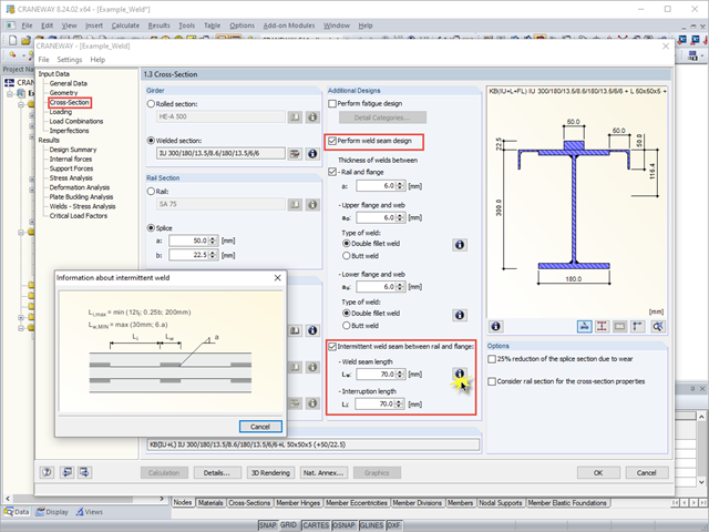
When using interrupted welds between the rail and flange, make sure that the applied weld length does not exceed the length of the rigid load application of the wheel load according to Equation 6.1 in [1].
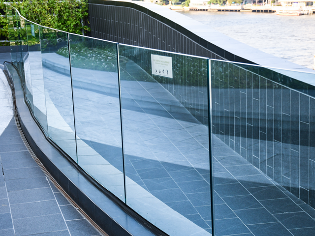
The architectural requirements for guardrails are still very high, and railings usually require a high degree of transparency. Glass railings, which do not require a visible support frame, offer a possible solution.
The proportion of glass used when planning a building is increasing. Open, light-flooded buildings represent the modern art of architecture. However, specialized engineers have to face new challenges during planning. One such example is ceiling-high glass facades loaded by a handrail. The influence of this loading, as well as the calculation of the deformation, are shown in this article.
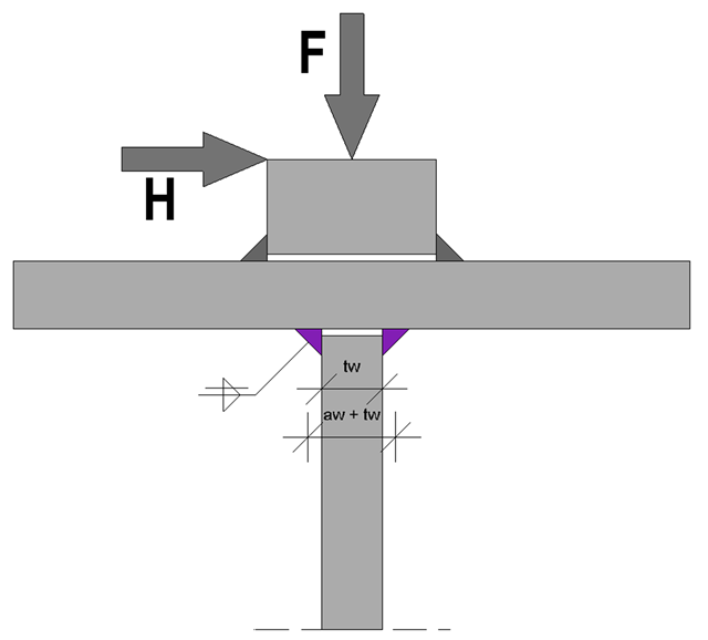
At the end of the topic on the design of welds on runway beams - after the technical articles about the rail weld seam in the ultimate limit state and the limit state of fatigue - a technical article about web fillet welds now follows. Both the ultimate limit state and the fatigue limit state are considered.
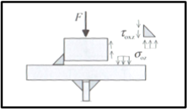
Based on the technical article about the ultimate limit state design of rail welds, the following explanation refers to the process of fatigue design of rail welds. In particular, this article explains in detail the effects of considering an eccentric wheel load of 1/4 of the rail head width.
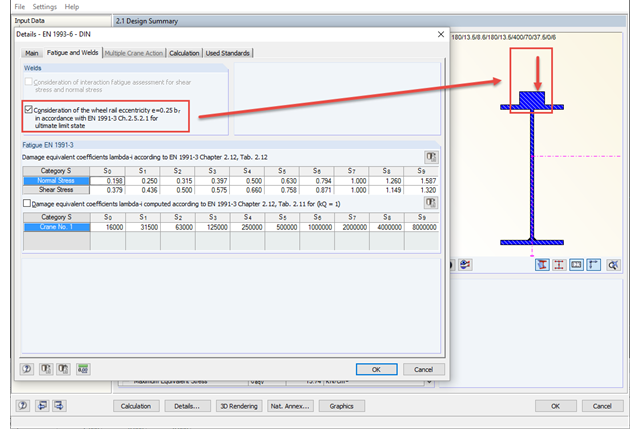
The eccentric wheel load application of 1/4 of the rail head width has to be considered only for fatigue design from damage class S3 according to DIN EN 1993‑6. An additional input option in detail settings allows you to consider this eccentricity for fatigue design at the ultimate limit state as well. By selecting this option, the design with the eccentric load applied is always considered without regard to the damage class.
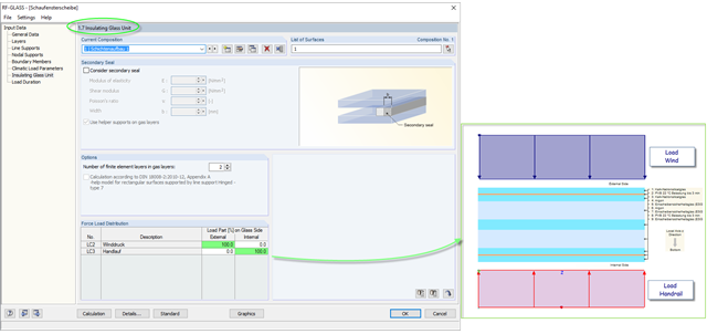
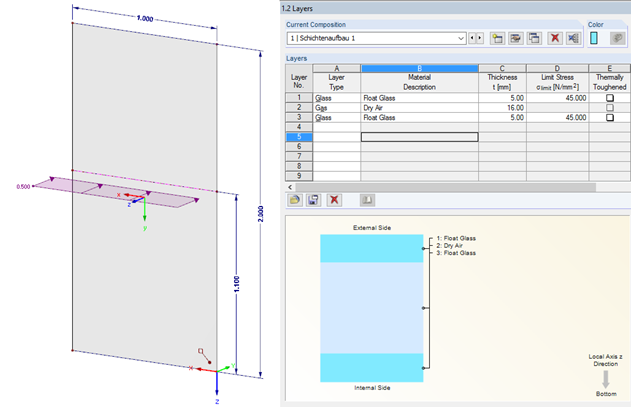
The insulating glass pane design places a special requirement on the load application point of the loading. For example, wind loads and loads due to fall protection may appear. For this, the wind load should be applied on the external glass side and the handrail load should act on the internal glass pane.
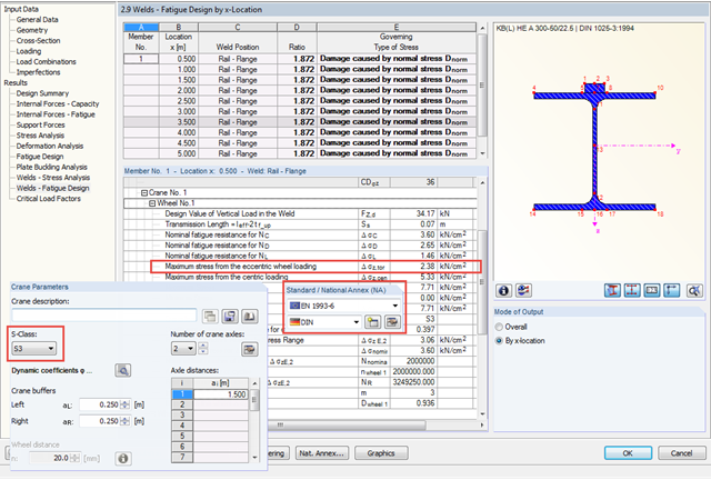
In CRANEWAY, the eccentric wheel loading of 1/4 of the rail head width is used for the fatigue design of welds as well as for craneway girder design according to the National Annex of Germany and as of damage class S3.
If crane runway girders are designed with flat steel rails, the welding of these rails is always a detail for the design. You can generally select between continuous and intermittent fillet welds as a rail fixing. The following article provides an overview of the design processes and their specific features, especially when using EN 1993-6.