Calculation Model
An insulated glass pane with a height of 2 m and a width of 1 m serves as an analysis model. The load application of the horizontal load of 0.5 kN amounts to 1.10 m. 5-16-5 insulated glass has been chosen as the pane structure.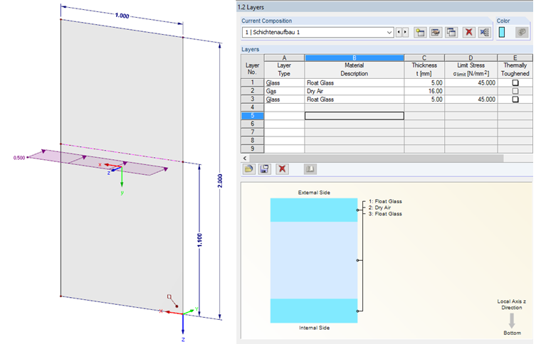
Calculation of Deformation
Due to the enclosed solid of the glass pane interspace, the design of both panes is rather complex. The loading of one pane inevitably also causes loading of the second pane due to the linked system and, therefore, a load distribution on both panes. The size of the load distribution depends on the selected pane structure or the stiffness of the single panes.FEM software (such as RFEM or RF-GLASS) is usually used to analyze insulated glass, which solves the structural problem. However, formulas for the analytical view are also shown in [1].
The following values result if the deformations are calculated manually for this example.
Calculation of solid under unit load
Calculation of auxiliary quantities
Pressure in the glass pane interspace
It is now possible to determine the deflection in the mid-span from these values.
From the distributed load
as well as from the internal load
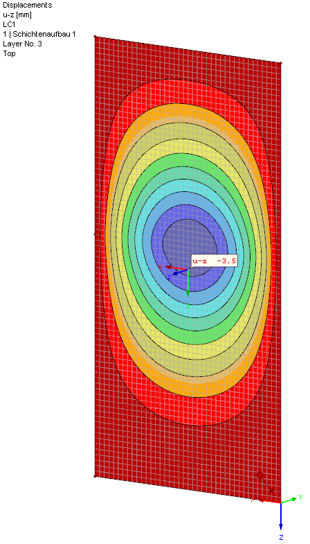
comes a resulting deformation of the loaded pane of
6.0 mm - 2.2 mm =3.8 mm.
This value corresponds almost exactly to the numerical calculation of RF-GLASS: uz = 3.5 mm. Small differences occur because the calculation formulas are linearized, and the program calculates according to the Large Deformation Theory and uses an approach of membrane load-bearing capacity.
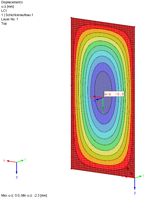
The secondary loaded pane is deformed by the prevailing gas pressure in the glass pane interspace. Since both panes have the same stiffness, this value has already been calculated with uz = 2.2 mm.