
- The proposed connection can be applied to all selected nodes in the structure
- The location of the connection can be defined using the 'Main' tab of the Add-on dialog box
- The design is performed for all connections in the structure and after the calculation, the results on all connections can be displayed
- The table shows the results for the individual connections, each connection is designed and can be saved separately

Complex Connection of Horizontal Beams to Column and Connection of Reinforcing Diagonals
The connection model was modeled using about 50 components. The model was created according to the real example of use in structure.
At first, the governing joint designs are arranged in groups and displayed with the basic geometry of the joint in the first result window. In the other result tables, you can see all fundamental design details such as the load-carrying capacity of anchors, stresses in welds, and others.
Dimensions, material specifications, and welds that are important for the construction of the connection are visible immediately and can be printed out. It is possible to visualize the connections in RF-/JOINTS Steel - Column Base or in the RFEM/RSTAB model.
All graphics can be included in the RFEM/RSTAB printout report or printed directly. Due to the scaled output, an optimal visual check is possible as early as in the design phase.

In the case of rectangular cross-sections, you can usually achieve a direct connection by using welds. However, you can also connect them to other cross-sections in the same way. Furthermore, other components such as end plates help you to connect the rectangular cross-sections to other structural components.

Steel bolted connections with gusset plates on the canopy structure.
Download the structural analysis model and open it with the finite element program RFEM 6 using Steel Joints Add-on.

In the Steel Joint add-on, you can design the connections of members with composite cross-sections. Furthermore, you can perform joint design checks for almost all thin-walled cross-sections in the RFEM library.
Go to Explanatory Video
Design of a frame connection with taper and stiffened members. A stress analysis and a buckling stability analysis were carried out for the connection. To display the buckling results, the connection was converted into a separate model.
The program supports you: It determines the bolt forces on the basis of the FE analysis model and evaluates them automatically. The add-on performs the standard-compliant design of bolt resistance for failure cases, such as tension, shear, hole bearing, and punching, and clearly displays all required coefficients.
Do you want to perform weld design? The welds are modeled as elastic-plastic surface elements, and their stresses are read out from the FE analysis model. The plasticity criteria is set in the way that they represent failure according to AISC J2-4, J2-5 (strength of welds), and J2-2 (strength of base metal). The design can be performed with the partial safety factors of the selected National Annex of EN 1993‑1‑8.
The plates in the connection are designed plastically by comparing the existing plastic strain to the allowable plastic strain. The default setting is 5% according to EN 1993‑1‑5, Annex C, but can be adjusted by user-defined specifications, as well as 5% for AISC 360.

Various design parameters of the cross-sections can be adjusted in the serviceability limit state configuration. The applied cross-section condition for the deformation and crack width analysis can be controlled there.
For this, the following settings can be activated:
- Crack state calculated from associated load
- Crack state determined as an envelope from all SLS design situations
- Cracked state of cross-section - independent of load

- Many predefined components: Allow easy input of typical connection situations, such as end plates, angles, multi-wall sheets, cleats, fin plates
- Universally applicable basic components (plates, welds, bolts, auxiliary planes) for entering complex connection situations
- Graphical display of the connection geometry that is updated in parallel with the input
- The Steel Joints Template included in the add-on allows you to select from several connection types and, and once selected, it will be applied to your model.
- Wide range of cross-section shapes: Includes I-sections, channel sections, angles, T-sections, built-up cross-sections, RHS (rectangular hollow sections), and thin-walled sections
- The Template covers connections from three general categories: Rigid, Pinned, Truss
- Automatic adaptation of the connection geometry, even if the structural components are subsequently edited, based on the relative relation of the components

You can perform the calculation of the warping torsion on the entire system. Thus, you consider the additional 7th degree of freedom in the member calculation. The stiffnesses of the connected structural elements are automatically taken into account. It means, you don't need to define equivalent spring stiffnesses or support conditions for a detached system.
You can then use the internal forces from the calculation with warping torsion in the add-ons for the design. Consider the warping bimoment and the secondary torsional moment, depending on the material and the selected standard. A typical application is the stability analysis according to the second-order theory with imperfections in steel structures.
Did you know that The application is not limited to thin-walled steel cross-sections. Thus, it is possible for you, for example, to perform the calculation of the ideal overturning moment of beams with solid timber cross-sections.

- The results of the connection design can be entered in the printout report
- When creating a new printout report, select the items added from the Steel Joints Add-on
- Use the tool 'Print Graphics to Printout Report' to insert graphics with the results of the connection, including the control panel, into the report
- Printout report contains the specifications of the connection components, design parameters, results and graphics
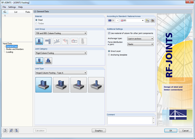
The Hinged Column Footing category provides four different base plate connections:
- Simple column base
- Tapered column base
- Column base for rectangular hollow sections
- Column base for circular hollow sections
The Restraint Column Footing category provides five different joint layouts of I-sections:
- Base plate without stiffening
- Base plate with stiffeners in center of flanges
- Base plate with stiffeners on both sides of column
- Base plate with channel sections
- Pocket foundation
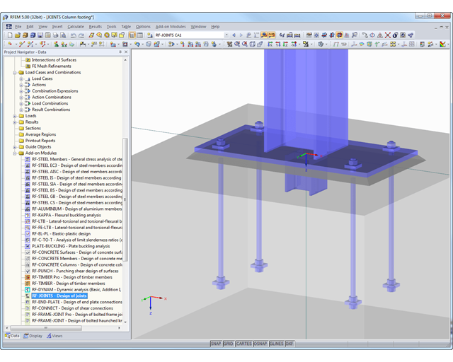
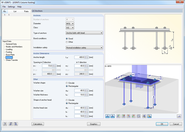
All connection types include a base plate welded around a steel column. Connections with anchors are set in concrete within the foundation. You can select anchor types M12 – M42 with steel grades of 4.6 – 10.9. The top and bottom sides of the anchors can be provided with round or angled sheets for better load distribution or anchorage. In addition, you can use rectangular or circular anchor heads with threads applied at the member ends.
The material and thickness of the grout layer, as well as the dimensions and material of the footing, can be set freely. Furthermore, you can define edge reinforcement of the footing. For a better transfer of shear forces, it is possible to arrange a shear key (cleat) on the bottom side of the base plate.
Shear forces are transferred by a cleat, anchors, or friction. You can combine the individual components.
After you have selected the anchorage type and the design standard in the first input window, define the node in Window 1.2 that is to be imported from RFEM/RSTAB and where the footing anchorage is to be designed.
Optionally, you can define the column cross-section and material manually. In the next input windows, you can define the parameters of the base point, such as The loading is imported from RFEM/RSTAB or, in the case of a manual joint definition, the loads are entered.
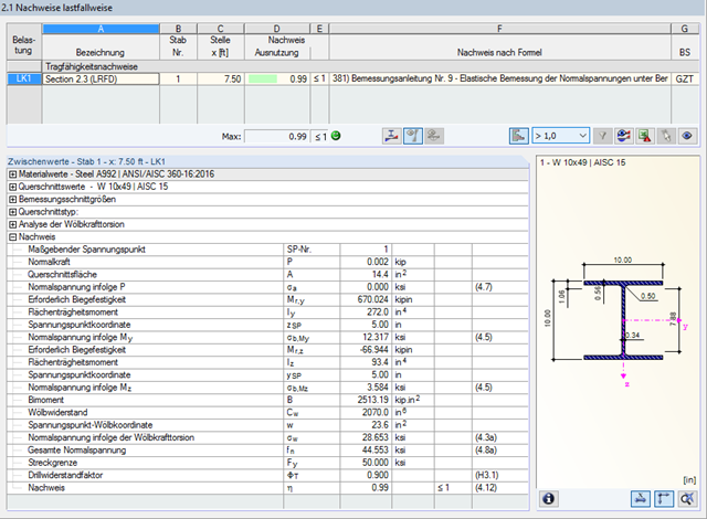
Due to the integrated RF-/STEEL Warping Torsion module extension, it is possible to perform the design according to Design Guide 9 in RF-/STEEL AISC.
The calculation is performed with 7 degrees of freedom according to the warping torsion theory and enables a realistic stability design, including consideration of torsion.

In the Steel Joints add-on, you can design connections according to the American standard ANSI/AISC 360‑16. The following design procedures are integrated:
- Load and Resistance Factor Design (LRFD)
- Allowable Stress Design (ASD)
- Consideration of 7 local deformation directions (ux, uy, uz, φx, φy, φz, ω) or 8 internal forces (N, Vu, Vv, Mt,pri, Mt,sec, Mu, Mv, Mω) when calculating member elements
- Usable in combination with a structural analysis according to linear static, second-order, and large deformation analysis (imperfections can also be taken into account)
- In combination with the Stability Analysis add-on, allows you to determine critical load factors and mode shapes of stability problems such as torsional buckling and lateral-torsional buckling
- Consideration of end plates and transverse stiffeners as warping springs when calculating I-sections with automatic determination and graphical display of the warping spring stiffness
- Graphical display of the cross-section warping of members in the deformation
- Full integration with RFEM and RSTAB

In the Steel Joints add-on, you can classify the joint stiffness.
In addition to the initial stiffness, the table also shows the limit values for hinged and rigid connections for the selected internal forces N, My, and/or Mz. The resulting classification is then displayed in tables as "hinged", "semi-rigid", or "rigid".
Go to Explanatory Video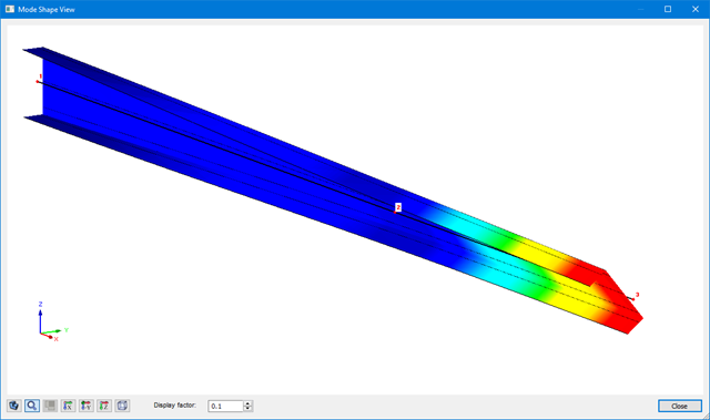
The results of warping torsion analysis are displayed in RF-/STEEL AISC and RF-/STEEL EC3 in the usual way. Among other results, the corresponding result windows include the critical warping and torsional values, internal forces, and design summary.
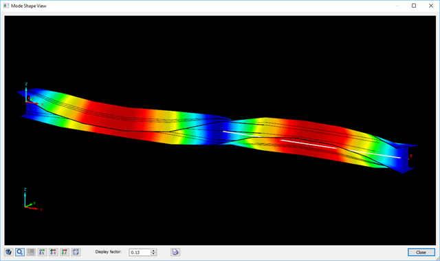
The graphical display of mode shapes (incl. warping) enables a realistic assessment of buckling behavior.

For joint components, you can check whether the stability failure is relevant. This requires the Structure Stability add-on for RFEM 6.
In this case, you calculate the critical load factor for all analyzed load combinations and the selected number of mode shapes for the connection model. Compare the smallest critical load factor with the limit value 15 from the standard EN 1993‑1‑1, Clause 5. Furthermore, you can make user-defined adjustment of the limit value. As a result of the stability analysis, the program displays the corresponding mode shapes graphically.
For the stability analysis, RFEM uses the adapted surface model to specifically recognize the local buckling shapes. You can also save and use the model of the stability analysis, including the results, as a separate model file.
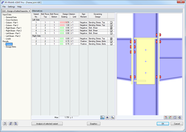
The RF-/FRAME-JOINT Pro add-on module performs the following designs according to the standards EN 1993-1-8 or DIN 18800:
- Beam end plate and column flange according to the plastic hinge theory
- Tension of bolts (including contact forces)
- Shearing of bolts
- Tension force introduction in column web and beam web
- Buckling analysis of gusset plate
- Shear design of gusset plate
- Compression force introduction in column web and buckling design of web plate
- If required:
- Design of diagonal stiffeners
- Web stiffener
- Supplementary web plates
- Compression force introduction in horizontal beam
- Design of welds
At first, the governing joint designs are arranged in groups and displayed with the basic geometry of the joint in the first result window. In the other result tables, you can see all fundamental design details such as the bearing resistance, shearing, sliding, and others.
Dimensions, material properties, and welds important for the connection construction are displayed immediately and can be printed directly. It is possible to visualize the connections in RF-/JOINTS Steel - Tower or in the RFEM/RSTAB model.
All graphics can be included in the RFEM/RSTAB printout report or printed directly. Due to the scaled output, an optimal visual check is possible as early as in the design phase.
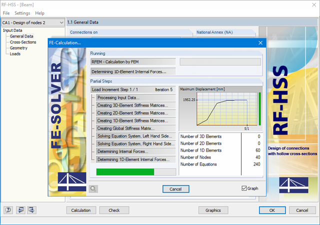
The determination of the critical buckling moment is carried out in RF-/STEEL AISC by using the eigenvalue solver which allows an exact determination of the critical buckling load.
The eigenvalue solver shows a display window of the eigenvalue graphics, which enables checking of the boundary conditions.

In the "Steel Joints" add-on, you can consider preloaded bolts in all components during the calculation. You can easily activate the preloading using the check box in the bolt parameters, and it has an impact on the stress-strain analysis as well as the stiffness analysis.
Preloaded bolts are special bolts used in steel structures to generate a high clamping force between the connected structural components. This clamping force causes friction between the structural components, which allows for the transfer of forces.
Functionality
Preloaded bolts are tightened with a certain torque, causing them to stretch and generate a tensile force. This tensile force is transferred to the connected components and leads to a high clamping force. The clamping force prevents the connection from loosening and ensures safe force transmission.
Advantages
- High load-bearing capacity: Preloaded bolts can transfer large forces.
- Low deformation: They minimize the deformation of the connection.
- Fatigue strength: They are resistant to fatigue.
- Easy assembly: They are relatively easy to assemble and disassemble.
Analysis and Design
The calculation of preloaded bolts is performed in RFEM using the FE analysis model generated by the "Steel Joints" add-on. It takes into account the clamping force, friction between structural components, shear strength of bolts, and load-bearing capacity of the structural components. The design is carried out according to DIN EN 1993‑1‑8 (Eurocode 3) or the US standard ANSI/AISC 360‑16. You can save the created analysis model, including the results, and use it as an independent RFEM model.

- For a new connection model, you have to select a node in the RFEM model
- After selecting a node, the members connected to the node are automatically recognized and assigned
- In the window for assigning members, select the ones that will be assigned to the connection
- The members marked by us are displayed in the preview window on the right
- Connections can be modeled for multiple nodes in a structure.
- For member settings, select the ones to be supported

- The program performs a plausibility check in parallel with the input to quickly detect missing entries or collisions.
- If an error occurs, an error message appears describing the problem.
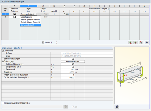
In STEEL AISC, it is possible to consider lateral intermediate supports at any location. For example, it is possible to stabilize only the upper flange.
Furthermore, user-defined lateral intermediate supports can be assigned; for example, single rotational springs and translational springs at any location at the cross-section.

- The design of the connection components is performed according to AISC 360 and Eurocode EN 1993‑1‑8.
- After activating the add-on, it is necessary to activate the design situations for Steel Connections in the "Load Cases and Combinations" dialog box.
- The design of the connection stability (buckling) requires the "Structure Stability" add-on.
- You can run the calculation using the table or the icon in the top bar.
A successful design check is based on the plausibility check of the geometric conditions.
The RF-/HSS add-on module performs the calculation for the following designs:
- Flange failure of chord member due to normal force
- Shear failure of chord member due to normal force
- Strut failure due to normal force
- Punching shear due to normal force

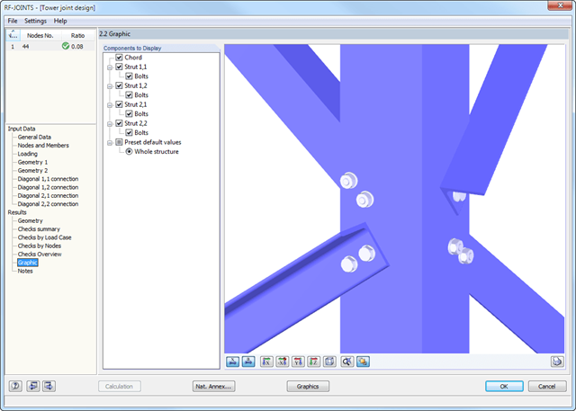
You can display all essential results on the FE model. In this case, you can filter the results separately according to the respective components.
Furthemore, RFEM delivers you all design checks in a tabular form, including the display of the formulas used. If you wish, you can transfer the result tables to the RFEM printout report.