
In the ultimate configuration of the steel joint design, you have the option to modify the limit plastic strain for welds.

The seismic design result is categorized into two sections: member requirements and connection requirements.
The "Seismic Requirements" include the Required Flexural Strength and the Required Shear Strength of the beam-to-column connection for moment frames. They are listed in the ‘Moment Frame Connection by Member’ tab. For braced frames, the Required Connection Tensile Strength and the Required Connection Compressive Strength of the brace are listed in the ‘Brace Connection by Member’ tab.
The program provides the performed design checks in tables. The design check details clearly display the formulas and references to the standard.

- Design of five types of seismic force-resisting systems (SFRS) includes Special Moment Frame (SMF), Intermediate Moment Frame (IMF), Ordinary Moment Frame (OMF), Ordinary Concentrically Braced Frame (OCBF), and Special Concentrically Braced Frame (SCBF)
- Ductility check of the width-to thickness ratios for webs and flanges
- Calculation of the required strength and stiffness for stability bracing of beams
- Calculation of the maximum spacing for stability bracing of beams
- Calculation of the required strength at hinge locations for stability bracing of beams
- Calculation of the column required strength with the option to neglect all bending moments, shear, and torsion for overstrength limit state
- Design check of column and brace slenderness ratios

The "Base Plate" component allows you to design base plate connections with cast-in anchors. In this case, plates, welds, anchorages, and steel-concrete interaction are analyzed.

- For the design according to Eurocode 3, the parameters of the National Annexes (NA) are integrated for the following countries:
-
 DIN EN 1993-1-1/NA:2016-04 (Germany)
 -
 ÖNORM EN 1993-1-1/NA:2015-12 (Austria)
 -
 SN EN 1993-1-1/NA:2016-07 (Switzerland)
 -
 BDS EN 1993-1-1/NA:2015-10 (Bulgaria)
 -
 BS EN 1993-1-1/NA:2016-07 (United Kingdom)
 -
 CEN EN 1993-1-1/2015-06 (European Union)
 -
 CYS EN 1993-1-1/NA:2015-07 (Cyprus)
 -
 CZE EN 1993-1-1/NA:2016-06 (Czech Republic)
 -
 DS EN 1993-1-1/NA:2015-07 (Denmark)
 -
 ELOT EN 1993-1-1/NA:2017-01 (Greece)
 -
 EVS EN 1993-1-1/NA:2015-08 (Estonia)
 -
 HRN EN 1993-1-1/NA:2016-03 (Croatia)
 -
 I S. EN 1993-1-1/NA:2016-03 (Ireland)
 -
 ILNAS EN 1993-1-1/NA:2015-06 (Luxembourg)
 -
 IST EN 1993-1-1/NA:2015-11 (Iceland)
 -
 LST EN 1993-1-1/NA:2017-01 (Lithuania)
 -
 LVS EN 1993-1-1/NA:2015-10 (Latvia)
 -
 MS EN 1993-1-1/NA:2010-01 (Malaysia)
 -
 MSZ EN 1993-1-1/NA:2015-11 (Hungary)
 -
 NBN EN 1993-1-1/NA:2015-07 (Belgium)
 -
 NEN EN 1993-1-1/NA:2016-12 (Netherlands)
 -
 NF EN 1993-1-1/NA:2016-02 (France)
 -
 NP EN 1993-1-1/NA:2009-03 (Portugal)
 -
 NS EN 1993-1-1/NA:2015-09 (Norway)
 -
 PN EN 1993-1-1/NA:2015-08 (Poland)
 -
 SFS EN 1993-1-1/NA:2015-08 (Finland)
 -
 SIST EN 1993-1-1/NA:2016-09 (Slovenia)
 -
 SR EN 1993-1-1/NA:2016-04 (Romania)
 -
 SS EN 1993-1-1/NA:2019-05 (Singapore)
 -
 SS EN 1993-1-1/NA:2015-06 (Sweden)
 -
 STN EN 1993-1-1/NA:2015-10 (Slovakia)
 -
 TKP EN 1993-1-1/NA:2015-04 (Belarus)
 -
 UNE EN 1993-1-1/NA:2016-02 (Spain)
 -
 UNI EN 1993-1-1/NA:2015-08 (Italy)
-
- The design according to US standard AISC 360 includes analysis methods according to:
-
 Load and Resistance Factor Design (LRFD)
 -
Allowable Stress Design (ASD)
-

The parameters of the National Annexes (NA) to Eurocode 3 of the following countries are integrated:
-
DIN EN 1993-1-1/NA:2016-04 (Germany)
-
ÖNORM EN 1993-1-1/NA:2015-12 (Austria)
-
SN EN 1993-1-1/NA:2016-07 (Switzerland)
-
BDS EN 1993-1-1/NA:2015-10 (Bulgaria)
-
BS EN 1993-1-1/NA:2016-07 (United Kingdom)
-
CEN EN 1993-1-1/2015-06 (European Union)
-
CYS EN 1993-1-1/NA:2015-07 (Cyprus)
-
CSN EN 1993-1-1/NA:2016-06 (Czech Republic)
-
DS EN 1993-1-1/NA:2015-07 (Denmark)
-
ELOT EN 1993-1-1/NA:2017-01 (Greece)
-
EVS EN 1993-1-1/NA:2015-08 (Estonia)
-
HRN EN 1993-1-1/NA:2016-03 (Croatia)
-
I S. EN 1993-1-1/NA:2016-03 (Ireland)
-
ILNAS EN 1993-1-1/NA:2015-06 (Luxembourg)
-
IST EN 1993-1-1/NA:2015-11 (Iceland)
-
LST EN 1993-1-1/NA:2017-01 (Lithuania)
-
LVS EN 1993-1-1/NA:2015-10 (Latvia)
-
MS EN 1993-1-1/NA:2010-01 (Malaysia)
-
MSZ EN 1993-1-1/NA:2015-11 (Hungary)
-
NBN EN 1993-1-1/NA:2015-07 (Belgium)
-
NEN EN 1993-1-1/NA:2016-12 (Netherlands)
-
NF EN 1993-1-1/NA:2016-02 (France)
-
NP EN 1993-1-1/NA:2009-03 (Portugal)
-
NS EN 1993-1-1/NA:2015-09 (Norway)
-
PN EN 1993-1-1/NA:2015-08 (Poland)
-
SFS EN 1993-1-1/NA:2015-08 (Finland)
-
SIST EN 1993-1-1/NA:2016-09 (Slovenia)
-
SR EN 1993-1-1/NA:2016-04 (Romania)
-
SS EN 1993-1-1/NA:2019-05 (Singapore)
-
SS EN 1993-1-1/NA:2015-06 (Sweden)
-
STN EN 1993-1-1/NA:2015-10 (Slovakia)
-
TKP EN 1993-1-1/NA:2015-04 (Belarus)
-
UNE EN 1993-1-1/NA:2016-02 (Spain)
-
UNI EN 1993-1-1/NA:2015-08 (Italy)

- Manual specification of critical component temperature or automatic determination of component temperature for desired duration
- A wide range of fire curves: standard temperature-time curve, external fire curve, hydrocarbon curve
- Manual adjustment of the essential coefficients for the determination of the steel temperature
- Consideration of hot-dip galvanizing of structural components for the determination of the steel temperature
- Results of a temperature-time diagram for the gas and steel temperature
- Fire protection cladding as a contour or a box cladding with temperature-independent materials can be considered when determining the temperature
- Design of members made of carbon steel or stainless steel
- Cross-section design checks and stability analyses (equivalent member method) according to EN 1993‑1‑2, Clause 4.2.3
- Design checks of the cross-sections of Class 4 according to EN 1993‑1‑2, Annex E.

- Calculation of deflections and comparison with the normative or manually adjusted limit values
- Consideration of a precamber for the deflection analysis
- Different limit values are possible, depending on the design situation type
- Manual adjustment of reference lengths and segmentation by direction
- Calculation of deflections related to the initial structure or to the deformed structure
- Further detailed design checks depending on the selected design standard (for example, limitation of web breathing according to EN 1993‑2)
- Graphical result display integrated in RFEM/RSTAB; for example, the design ratio of a limit value, the deformation, or the sag
- Complete integration of the results into the RFEM/RSTAB printout report
_(1).png?mw=640&hash=415f7bbaf70e41679bb0106e1cf91eaa8c493ec9)
- Automatic generation of FE analysis models: The add-on automatically creates a finite element model (FE) of the steel connection in the background.
- Consideration of all internal forces: The calculation and design checks include all internal forces (N, Vy, Vz, My, Mz, MT) and are not limited to planar loading.
- Automatic load transfer: All load combinations are automatically transferred to the FE analysis model of the connection. The loads are transferred directly from RFEM, so manual data input is not necessary.
- Efficient modeling: The add-on saves you time when modeling complex connection situations. You can also save the created FE analysis model and use it further for your own detailed analyses.
- Extensible library: An extensive and extensible library with predefined steel connection templates is available.
- Wide applicability: The add-on is suitable for connections of any type and shape, compatible with almost all rolled, welded, built-up, and thin-walled cross-sections.

- Cross-section optimization
- Transfer of optimized sections to RFEM/RSTAB
- Design of any thin-walled section from RSECTION
- Representation of a stress diagram on a section
- Determination of normal, shear, and equivalent stresses
- Output of stress components for the individual member internal force types
- Detailed representation of stresses in all stress points
- Determination of the largest Δσ for each stress point (for example, for fatigue design)
- Colored display of stresses and design ratios for a quick overview of the critical or oversized zones
- Output of parts lists

In the Concrete Design provides an option to perform seismic design according to AISC 341-16 for steel members.
Five SFRS types (Seismic Force-Resisting Systems) are available for this.
More Information
You enter the structural system and calculate the internal forces in the programs RFEM and RSTAB. You have full access to the extensive material and cross-section libraries. Did you know? You can also use the RSECTION program to create general cross-sections.
You find Steel Design fully integrated in the main programs. They automatically take into account the structure and the available calculation results. You can assign further entries for the aluminum design, such as effective lengths, cross-section reductions, or design parameters, to the objects to be designed. At many places of the program, you can easily select the elements graphically using the [Select] function.

- A wide range of available sections, such as rolled I-sections; channel sections; T-sections; angles; rectangular and circular hollow sections; round bars; symmetrical and asymmetrical, parametric I-, T-, and angle sections; built-up cross-sections (suitability for design depends on the selected standard)
- Design of general RSECTION cross-sections (depending on the design formats available in the respective standard); for example, equivalent stress design
- Design of tapered members (design method depending on the standard)
- Adjustment of the essential design factors and standard parameters is possible
- Flexibility due to detailed setting options for basis and extent of calculations
- Fast and clear results output for an immediate overview of the result distribution after the design
- Detailed output of the design results and essential formulas (comprehensible and verifiable result path)
- Numerical results clearly arranged in tables and graphical display of the results in the model
- Integration of the output into the RFEM/RSTAB printout report

The design checks for the members you have selected are carried out taking into account the governing component temperature. You can perform the cross-section design checks and stability analyses according to EN 1993‑1‑2, Section 4.2.3, in the Steel Design add-on. All reduction factors and coefficients that are necessary are stored accordingly and are taken into account when determining the load-bearing capacity.
The effective lengths for the equivalent member design are taken directly from the strength entries. You don't need to enter them again.
In each design, perform the cross-section classification first. For the cross-sections of Class 4, the design is performed automatically according to EN 1993‑1‑2, Annex E.

Is a clear arrangement important for you? The program provides you with a clear overview of all performed design checks for the design standard. For each design check, it is necessary to determine a design criterion. There are also design details arranged in a structured way, including the initial values, intermediate results, and final results. You can laso find here an information window where the calculation process with the applied formulas, standard sources, and results is displayed in great detail.

You can individually define all reference lengths that need to be considered in the calculation of the deflection limit value, as well as the segments to be checked, depending on the direction. For this, define design supports at the intermediate nodes of a member and assign them to the respective direction for the deformation analysis. Thus, the segments are created where it is possible to define a precamber for each direction and segment.

- General stress analysis
- Automatic import of internal forces from RFEM/RSTAB
- Graphical and numerical output of stresses, strains, clearance, and design ratios fully integrated in RFEM/RSTAB
- User-defined specification of the limit stress
- Summary of similar structural components for the design
- Wide range of customization options for graphical output
- Clearly arranged result tables for a quick overview after the design
- Simple traceability of the results due to the complete documentation of the calculation method including all formulas
- High productivity due to the minimal amount of input data required
- Flexibility due to detailed setting options for basis and extent of calculations
- Gray zone display for unimportant value ranges (see Product Feature)

You can find the design checks directly in the Steel Design add-on. They are available there in a tabular form. You can also display the distribution of the design ratios graphically. Both the table and the graphical output provide you with the extensive filter options. You can thus specifically display the desired design checks by limit state or by design type.
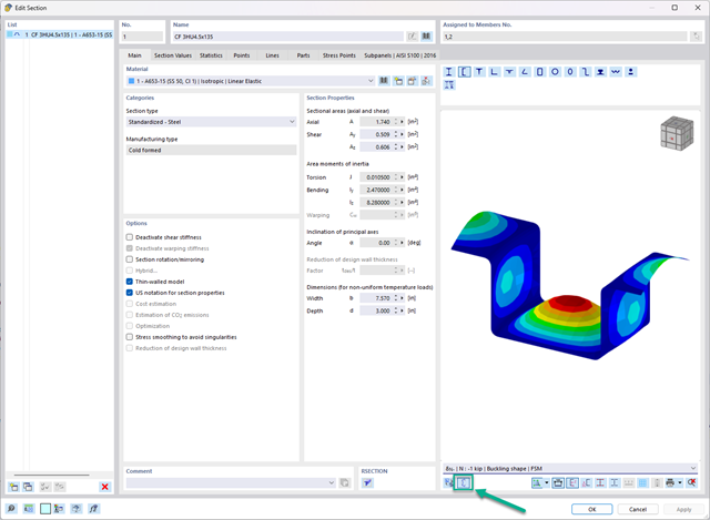
In the "Edit Section" dialog box, you can display the buckling shapes of the Finite Strip Method (FSM) as a 3D graphic.
For the design according to Eurocode 3, the parameters of the National Annexes (NA) are integrated for the following countries:
-
DIN EN 1993-1-1/NA:2020-11 (Germany)
-
ÖNORM EN 1993-1-1/NA:2015-12 (Austria)
-
SN EN 1993-1-1/NA:2016-07 (Switzerland)
-
BDS EN 1993-1-1/NA:2015-10 (Bulgaria)
-
BS EN 1993-1-1/NA:2016-07 (United Kingdom)
-
CEN EN 1993-1-1/2015-06 (European Union)
-
CYS EN 1993-1-1/NA:2015-07 (Cyprus)
-
CZE EN 1993-1-1/NA:2016-06 (Czech Republic)
-
DS EN 1993-1-1/NA:2015-07 (Denmark)
-
ELOT EN 1993-1-1/NA:2017-01 (Greece)
-
EVS EN 1993-1-1/NA:2015-08 (Estonia)
-
HRN EN 1993-1-1/NA:2016-03 (Croatia)
-
I S. EN 1993-1-1/NA:2016-03 (Ireland)
-
ILNAS EN 1993-1-1/NA:2015-06 (Luxembourg)
-
IST EN 1993-1-1/NA:2015-11 (Iceland)
-
LST EN 1993-1-1/NA:2017-01 (Lithuania)
-
LVS EN 1993-1-1/NA:2015-10 (Latvia)
-
MS EN 1993-1-1/NA:2010-01 (Malaysia)
-
MSZ EN 1993-1-1/NA:2015-11 (Hungary)
-
NBN EN 1993-1-1/NA:2015-07 (Belgium)
-
NEN EN 1993-1-1/NA:2016-12 (Netherlands)
-
NF EN 1993-1-1/NA:2016-02 (France)
-
NP EN 1993-1-1/NA:2009-03 (Portugal)
-
NS EN 1993-1-1/NA:2015-09 (Norway)
-
PN EN 1993-1-1/NA:2015-08 (Poland)
-
SFS EN 1993-1-1/NA:2015-08 (Finland)
-
SIST EN 1993-1-1/NA:2016-09 (Slovenia)
-
SR EN 1993-1-1/NA:2016-04 (Romania)
-
SS EN 1993-1-1/NA:2019-05 (Singapore)
-
SS EN 1993-1-1/NA:2015-06 (Sweden)
-
STN EN 1993-1-1/NA:2015-10 (Slovakia)
-
TKP EN 1993-1-1/NA:2015-04 (Belarus)
-
UNE EN 1993-1-1/NA:2016-02 (Spain)
-
UNI EN 1993-1-1/NA:2015-08 (Italy)

After completing the design, the Dlubal Software presents the fire resistance design checks clearly and with all result details. This makes the results comprehensible in detail. Furthermore, the results also contain all the parameters required for the determination of the component temperature at the design time.
You can also specifically evaluate the temperature distribution in the structural component using the temperature-time diagram.
All result tables and graphics, including the ultimate and serviceability limit state results, can be integrated into the global printout report of RFEM/RSTAB as a part of the steel design results.

In the Steel Joints add-on, you can perform precise cuts on plates and structural components using the "Auxiliary Solid" component. Within this component, you can use the shapes of a box, a cylinder, or any cross-section as a guide object.
Go to Explanatory Video
- Selection of nodes in the RFEM model, automatic recognition and assignment of the members connected to the node
- Many predefined components available for easy input of typical connection situations (for example, end plates, cleats, fin plates)
- Universally applicable basic components (plates, welds, auxiliary planes) for entering complex connection situations
- No manual editing of the FE model required by the user, the essential calculation settings can be changed via the configuration settings
- Automatic adaptation of the connection geometry, even if the members are subsequently edited, due to the relative relation of the components to each other
- Parallel to the input, a plausibility check is carried out by the program to quickly detect missing input or collisions, for example
- Graphical display of the connection geometry that is updated in parallel with the input

In the Member Editor component, you can also select the entire member as the modifying object instead of the individual member plates. This way, you can apply both operations "Notch" and "Chamfer" to several member plates.

The structural analysis programs RFEM/RSTAB offer you a wide range of automated functions that make your dayily work easier. One of them is the automatic generation of load and result combinations for the accidental design situation of fire design. The members to be designed with the corresponding internal forces are imported directly from RFEM/RSTAB. You don't need to do anything else. The program has also already stored all information about the material and cross-section for you.
By assigning a fire resistance configuration to the members to be designed, you define the parameters relevant for the fire resistance design. Here you can manually specify the critical steel temperature at the design time. Or let the program to determine the temperature determined automatically for a specified fire duration. You can select from various fire temperature curves and fire protection measures. It is also possible to make further detailed settings, such as the definition of the fire exposure on all sides or three sides

Was your design successful? Just sit back and relax. The program gives you the performed design checks in tables. All result details are displayed for you and you can easily follow them using the clearly arranged design formulas.
The design checks are carried out at all governing locations of the members. A graphical display is provided as a result diagram. Furthermore, you have access to detailed graphics, such as the stress distribution on a cross-section or the governing mode shape, available in the result output.
All input and result data are part of the RFEM/RSTAB printout report. You can select the report contents and extent specifically for the individual design checks.
The component temperature to be applied at the design time is determined automatically. You can adjust the coefficients used to determine the temperature. In this step, it is best for you to also select the hot-dip galvanizing. According to the DASt Guideline 027 "Determination of Component Temperature of Hot-Dip Galvanized Steel Components in Case of Fire", a lower emissivity of the steel surface is applied up to a limit temperature. Overall, this gives you a lower temperature for the thus more favorable fire resistance design.
Perform the fire resistance design with a reduced load-bearing capacity according to the component temperature determined automatically right at the design time. You can determine this automatically according to various temperature curves in the program (a standard temperature-time curve, an external fire curve, a hydrocarbon curve). For other types of temperature determination, it is also possible for you to manually specify the temperature to be applied in the design. You can determine this, for example, according to the parametric temperature-time curve from DIN EN 1991‑1‑2 or from a fire protection report.

- Determination of principal and basic stresses, membrane and shear stresses, as well as equivalent stresses and equivalent membrane stresses
- Stress analysis for structural surfaces including simple or complex shapes
- Equivalent stresses calculated according to different approaches:
- Shape modification hypothesis (von Mises)
- Shear stress hypothesis (Tresca)
- Normal stress hypothesis (Rankine)
- Principal strain hypothesis (Bach)
- Optional optimization of surface thicknesses and data transfer to RFEM
- Output of strains
- Detailed results of individual stress components and ratios in tables and graphics
- Filter function for solids, surfaces, lines, and nodes in tables
- Transversal shear stresses according to Mindlin, Kirchhoff, or user-defined specifications
- Stress evaluation for welds at connection lines between surfaces (see the Product Feature)

- Design of tension, compression, bending, shear, torsion, and combined internal forces
- Tension design with consideration of a reduced section area (for example, hole weakening)
- Automatic classification of cross-sections to check local buckling
- Internal forces from the calculation with Torsional Warping (7 DOF) are taken into account by means of the equivalent stress check (currently not for the design standards AISC 360‑16 and GB 50017).
- Design of cross-sections of Class 4 with effective cross-section properties according to EN 1993‑1‑3 (licenses for RSECTION and Effective Sections are required for the RSECTION cross-sections)
- Shear buckling check according to EN 1993‑1‑5 with consideration of transverse stiffeners
- Design of stainless steel components according to EN 1993‑1‑4