
The "Base Plate" component allows you to design base plate connections with cast-in anchors. In this case, plates, welds, anchorages, and steel-concrete interaction are analyzed.

Do you work with the structural components consisting of slabs? In that case, you have to perform the shear force design with the requirements of punching shear design, for example, according to 6.4, EN 1992‑1‑1. In addition to floor slabs, you can also design foundation slabs in this way.
In the Ultimate Configuration for concrete design, you can define the punching design parameters for the selected nodes.
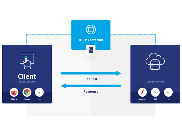
WebService and API provide you various scope of application. We have summarized some ideas as to how WebService and API can support your company:
- Creating additional applications for RFEM 6, RSTAB 9, and RSECTION 1
- Possibility to make the workflows more efficient (for example, model definition and input) and to integrate RFEM 6, RSTAB 9, and RSECTION 1 into your company applications
- Simulating and calculating several design options
- Running optimization algorithms for size, shape, and/or topology
- Accessing the calculation results
- Generation of printout reports in the PDF format
The level of quality of the work is automatically increased not only by the algorithmic model definitions, but also by:
- Extending / consolidating RFEM 6, RSTAB 9, and RSECTION 1 with your own controls
- Increased interoperability between the individual software used to complete a project

Compared to the RF‑/DYNAM Pro - Natural Vibrations add-on module (RFEM 5 / RSTAB 8), the following new features have been added to the Modal Analysis add-on for RFEM 6 / RSTAB 9:
- Preset combination coefficients for various standards (EC 8, ASCE, and so on)
- Optional neglect of masses (for example, mass of foundations)
- Methods for determining the number of mode shapes (user-defined, automatic - to reach effective modal mass factors, automatic - to reach the maximum natural frequency)
- Output of modal masses, effective modal masses, modal mass factors, and participation factors
- Masses in mesh points displayed in tables and graphics
- Various scaling options for mode shapes in the Result navigator

- Automatic consideration of masses from self-weight
- Direct import of masses from load cases or load combinations
- Optional definition of additional masses (nodal, linear, or surface masses, as well as inertia masses) directly in the load cases
- Optional neglect of masses (for example, mass of foundations)
- Combination of masses in different load cases and load combinations
- Preset combination coefficients for various standards (EC 8, SIA 261, ASCE 7,...)
- Optional import of initial states (for example, to consider prestress and imperfection)
- Structure Modification
- Consideration of failed supports or members/surfaces/solids
- Definition of several modal analyses (for example, to analyze different masses or stiffness modifications)
- Selection of mass matrix type (diagonal matrix, consistent matrix, unit matrix), including user-defined specification of translational and rotational degrees of freedom
- Methods for determining the number of mode shapes (user-defined, automatic - to reach effective modal mass factors, automatic - to reach the maximum natural frequency - only available in RSTAB)
- Determination of mode shapes and masses in nodes or FE mesh points
- Results of eigenvalue, angular frequency, natural frequency, and period
- Output of modal masses, effective modal masses, modal mass factors, and participation factors
- Masses in mesh points displayed in tables and graphics
- Visualization and animation of mode shapes
- Various scaling options for mode shapes
- Documentation of numerical and graphical results in printout report

- Realistic representation of interaction between a building and soil
- Realistic representation of the influences of the foundation components on each other
- Extensible library of soil properties
- Consideration of several soil samples (probes) at different locations, even outside the building
- Determination of settlements and stress diagrams as well as their graphical and tabular display
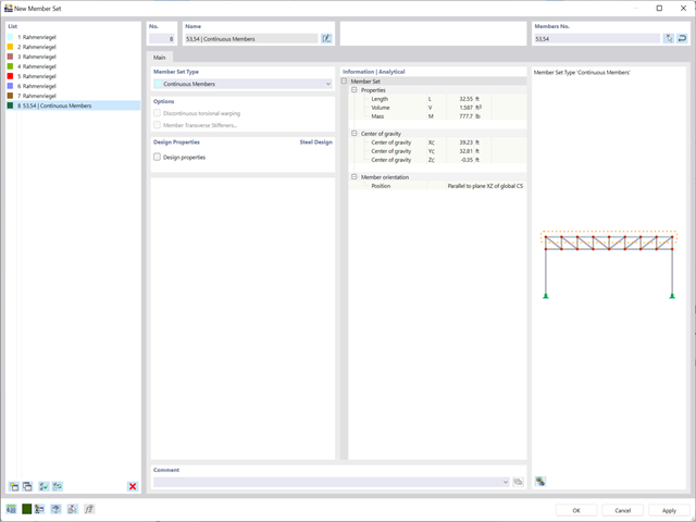
Planning with members is also facilitated in the programs due to specific features. You can arrange members eccentrically, support them by elastic foundations, or define them as rigid links. Member sets allow you to easily apply the load on several members.
In RFEM, you can also define eccentricities of surfaces. Here, you can transform nodal and linear loads into surface loads. If necessary, divide surfaces into surface components and members into surfaces.
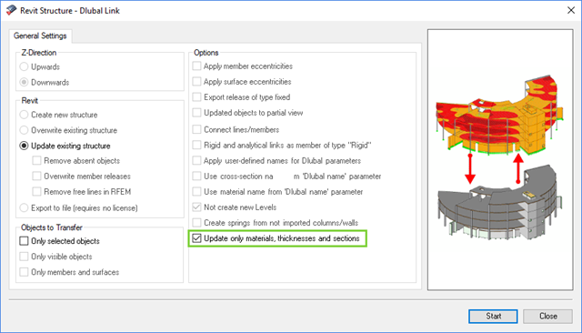
The direct interface with Revit allows you to update the Revit model according to the changes you have made in RFEM or RSTAB. Depending on the modification, the Revit objects may have to be regenerated (deleting the object and subsequent regeneration). The regeneration is performed on the basis of the RFEM/RSTAB model.
If you want to avoid this regeneration, activate the check box 'Update only materials, thicknesses, and sections'. In this case, only the properties of the objects will be adjusted. Changes different from those in material, surface thickness, and section are, however, not considered in this case.
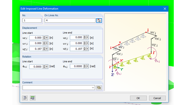
Imposed line deformations can be defined for supported lines in RFEM. For example, foundation settlements can be simulated with this function.
Moreover, it is possible to define imposed rotations for lines.
All design results and design checks are displayed in detail and in a comprehensible manner. An error log indicates non-designable situations or failed recommendations. Due to the permanent integration in RFEM/RSTAB, subsequent modifications in the structural system and in loading are automatically taken into account for the connections to be checked.
If one of the designs could not be fulfilled, the corresponding line is highlighted in red. The output appears in a short or a long form in the global printout report of RFEM/RSTAB. Furthermore, you can easily export all result tables to MS Excel or in a CSV file. A special transfer menu defines all specifications required for the export.
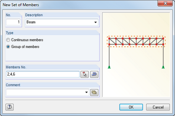
Members can be arranged eccentrically, supported by elastic foundations, or defined as rigid links. Member sets facilitate the load application on several members.
In RFEM, you can also define eccentricities of surfaces. Here, it is possible to transform nodal and linear loads into surface loads. You can divide surfaces into surface components and members into surfaces.
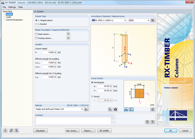
RX- TIMBER Column designs hinged columns (optionally with elastic head or footing restraint) and brackets (optionally with elastic foundation of the footing column).
For this, circular and rectangular cross‑sections are available in the program.
RX-TIMBER Column | Design of Timber Columns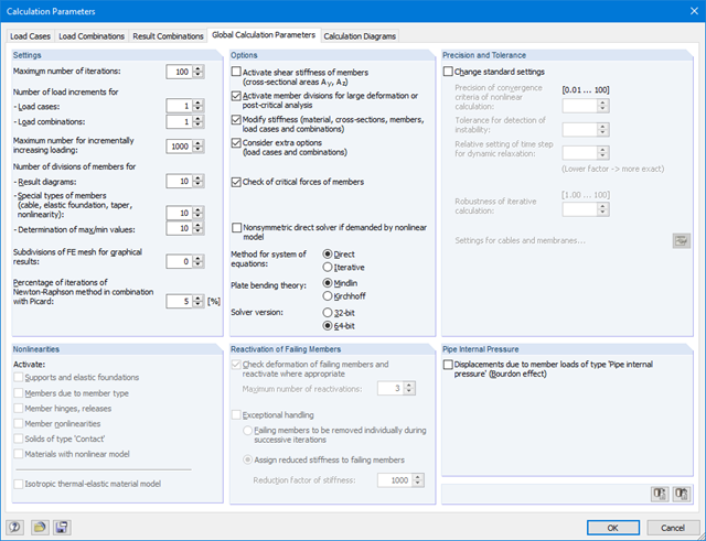
Several methods are available for the eigenvalue analysis:
- Direct Methods
- The direct methods (Lanczos, roots of characteristic polynomial, subspace iteration method) are suitable for small to medium-sized models. These fast methods for equation solvers benefit from a lot of the computer memory (RAM). 64-bit systems use more memory so that even bigger structural systems can be calculated quickly.
- ICG iteration method (Incomplete Conjugate Gradient)
- This method requires only a small amount of memory. Eigenvalues are determined one after the other. It can be used to calculate large structural systems with few eigenvalues.
The RF-STABILITY add-on module can also perform the non-linear stability analysis. Also for nonlinear structures, results close to reality are provided. The critical load factor is determined by gradually increasing the loads of the underlying load case until the instability is reached. The load increment takes into account nonlinearities such as failing members, supports and foundations, and material nonlinearities.
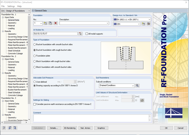
- Available types of foundation:Pure foundation plate (optionally without reinforcement)
- Bucket foundation with smooth bucket sides
- Bucket foundation with rough bucket sides
- Block Foundation with Smooth Bucket Sides
- Block foundation with rough bucket sides
- Design according to EN 1992-1-1 and EN 1997-1
- The following National Annexes of Eurocode 2 and Eurocode 7 are available:
-
 DIN EN 1992-1-1/NA/A1:2015-12 | DIN EN 1997-1/NA:2010-12
 -
 ÖNORM B 1992-1-1:2018-01 | ÖNORM B 1997-1:2007-11
 -
 DK EN 1992-1-1/NA:2013 | DK EN 1997-1/NA:2007
 -
 BDS EN 1992-1-1:2005/NA:2011 | BDS EN 1997-1:2005/NA:2012
 -
 SFS EN 1992-1-1/NA:2007-10 | SFS EN 1997-1/NA:2004-01
 -
 NF EN 1992-1-1/NA:2016-03 | NF EN 1997-1/NA:2006-09
 -
 UNI EN 1992-1-1/NA:2007-07 | DIN EN 1997-1/NA:2005-01
 -
 NEN EN 1992-1-1 C2:2011/NB:2016-11 | NEN EN 1997-1+C1:2012/NB:2012
 -
 PN EN 1992-1-1/NA:2010 | PN EN 1997-1/NA:2005-05
 -
 STN EN 1992-1-1/NA:2008-06 | STN EN 1997-1/NA:2005-10
 -
 SIST EN 1992-1-1:2005/A101:2006 | SIST EN 1997-1/NA:2006-03
 -
 UNE EN 1992-1-1/NA:2013 | UNE EN 1997-1:2010
 -
 EN 1992-1-1/NA:2008 | Svensk EN 1997-1:2005/AC:2009
 -
 CSN EN 1992-1-1/NA:2016-05 | CSN EN 1997-1/NA:2014-06
 -
 BS EN 1992-1-1:2004/NA:2005 | BS EN 1997-1:2004
 -
 TKP EN 1992-1-1:2009 | TKP EN 1997-1:2009
 -
 CYS EN 1992-1-1:2004/NA:2009 | CYS EN 1997‑1/NA:2004
-
In addition to the National Annexes (NA) listed above, you can also define a specific NA, applying user‑defined limit values and parameters.
- Automatic calculation of governing loading from load cases
- Specification of additional support forces
- Determination of the reinforcement proposal for the bottom and top plate reinforcement considering the most favorable combination of mat and rebars
- Individual adjustment of reinforcement proposal
- Results of foundation reinforcement in detailed reinforcement drawings
- Results displayed in tables and graphics
- Visualization of foundation, columns, and reinforcement in 3D rendering

You can select several methods that are available for the eigenvalue analysis:
- Direct Methods
- The direct methods (Lanczos [RFEM], roots of characteristic polynomial [RFEM], subspace iteration method [RFEM/RSTAB], and shifted inverse iteration [RSTAB]) are suitable for small to medium-sized models. You should only use these fast solver methods if your computer has a larger amount of memory (RAM).
- ICG Iteration Method (Incomplete Conjugate Gradient [RFEM])
- In contrast, this method only requires a small amount of memory. Eigenvalues are determined one after the other. It can be used to calculate large structural systems with few eigenvalues.
Use the Structure Stability add-on to perform a nonlinear stability analysis using the incremental method. This analysis delivers close-to-reality results also for nonlinear structures. The critical load factor is determined by gradually increasing the loads of the underlying load case until the instability is reached. The load increment takes into account nonlinearities such as failing members, supports and foundations, and material nonlinearities. After increasing the load, you can optionally perform a linear stability analysis on the last stable state in order to determine the stability mode.
Comprehensive and easy options in the individual input windows facilitate the representation of the structural system:
Nodal Supports
- The support type of each node is editable.
- It is possible to define a warp stiffening on each node. The resulting warp spring is determined automatically using the input parameters.
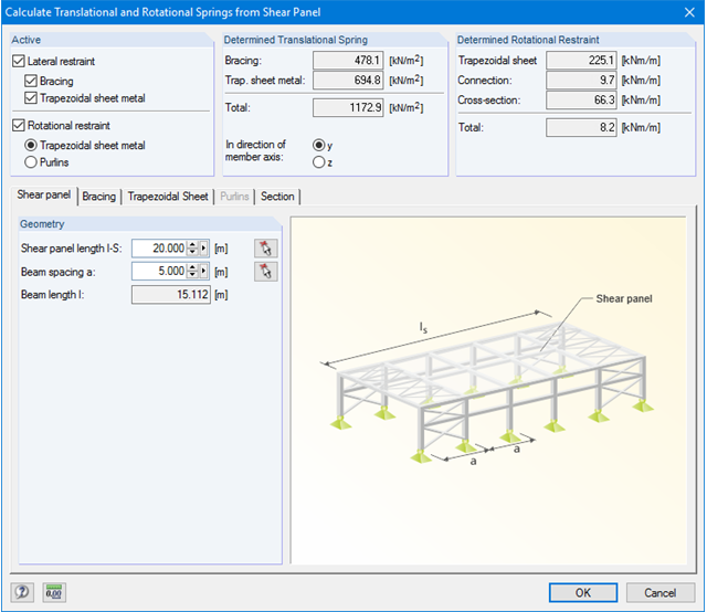
Elastic member foundation
- In the case of elastic member foundations, you can manually enter spring constants.
- Alternatively, you can use the various options to define the rotational and translational springs from a shear panel.
Member End Springs
- RF-/FE-LTB calculates the individual spring constants automatically. You can use the dialog boxes and detailed pictures to represent a translational spring by connecting component, a rotational spring by a connecting column, or a warping stiffener (available types: end plate, channel section, angle, connecting column, cantilevered portion).
Member Hinges
- If there are no member hinges defined in RFEM/RSTAB for the set of members, you can define them directly in the RF-/FE-LTB add-on module.
Load Data
- The nodal and member loads of the selected load cases and combinations are displayed in separate windows. There you can edit, delete, or add them individually.
Imperfections
- RF-/FE-LTB automatically applies the imperfections by scaling the lowest eigenvector.
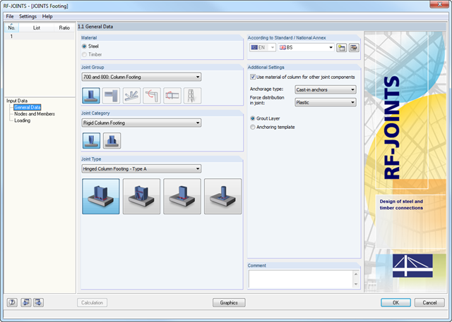
The Hinged Column Footing category provides four different base plate connections:
- Simple column base
- Tapered column base
- Column base for rectangular hollow sections
- Column base for circular hollow sections
The Restraint Column Footing category provides five different joint layouts of I-sections:
- Base plate without stiffening
- Base plate with stiffeners in center of flanges
- Base plate with stiffeners on both sides of column
- Base plate with channel sections
- Pocket foundation
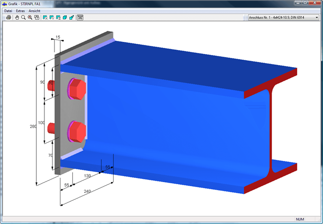
All connection types include a base plate welded around a steel column. Connections with anchors are set in concrete within the foundation. You can select anchor types M12 – M42 with steel grades of 4.6 – 10.9. The top and bottom sides of the anchors can be provided with round or angled sheets for better load distribution or anchorage. In addition, you can use rectangular or circular anchor heads with threads applied at the member ends.
The material and thickness of the grout layer, as well as the dimensions and material of the footing, can be set freely. Furthermore, you can define edge reinforcement of the footing. For a better transfer of shear forces, it is possible to arrange a shear key (cleat) on the bottom side of the base plate.
Shear forces are transferred by a cleat, anchors, or friction. You can combine the individual components.
Foundations are assigned graphically by selecting supports using the [Select] function in the graphical user interface of RFEM/RSTAB and by specifying the load cases to be designed. You can define all other foundation details quickly and easily in clearly arranged input windows.
In addition to all support forces from RFEM/RSTAB, you can specify further loads to be considered when dimensioning the foundations. The following additional loadings are available:
- Pemanent surface load due to earth covering
- Negative surface load; for example, due to traffic
- Ground water level for uplift consideration
- Concentrated loads in any position on the foundation plate
- Line loads with any distribution over the foundation plate
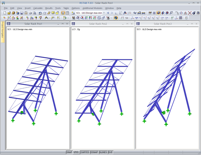
A basic model is created and saved under different names depending on the construction progress. These structural models are then used for the supercombination. The superpositioning can be performed in the same way as for an RSTAB result combination.
By modeling various construction or operational conditions, different geometric boundary conditions can be represented: It is possible to add or remove supports, members, or elastic foundation of the model, for example.
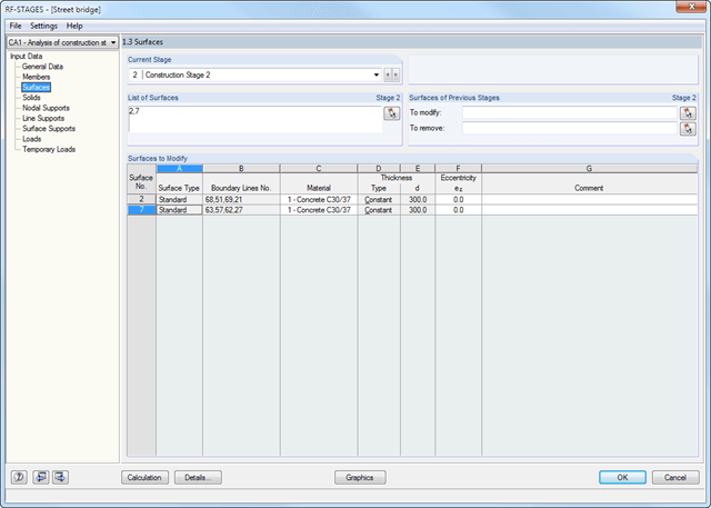
- Simple definition of construction stages in the RFEM/RSTAB structure including visualization
- Addition, removal, and modification of member, surface, and solid properties (such as member hinges, surface eccentricities, degrees of freedom for supports, and others)
- Optional superposition of construction stages with additional temporary loads; for example, mounting loads or mounting cranes, and others
- Consideration of nonlinear effects such as failure of a tension member, elastic foundations, or nonlinear supports
- Numerical and graphical result display for individual construction stages or as an envelope (Max/Min) of all construction stages
- Detailed printout report including all structural and load data of each construction stage
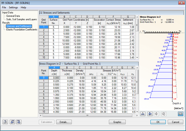
The calculated stresses and settlements are displayed in result windows. In addition, it is possible to evaluate the results graphically. The graphic displays the position and the layer arrangement of the soil samples to clarify the results.
The final result window shows the elastic foundation coefficients. Graphical evaluation is possible as well.
Elastic foundation coefficients are calculated according to the non-linear iterative method. The module determines elastic foundation coefficients for each individual element. They are dependent on the deformation.
The program creates a reinforcement proposal for the top and the bottom plate reinforcement. The program searches automatically for the most favorable reinforcement combination, with a mat and added rebars. If required, the rebars are distributed across two reinforcement areas by curtailment. It is possible to modify the reinforcement proposal individually by:
- Application of another mat type
- Individual control of diameter and spacing of added rebars
- Free selection of reinforcement area widths
- Individual curtailment of reinforcements
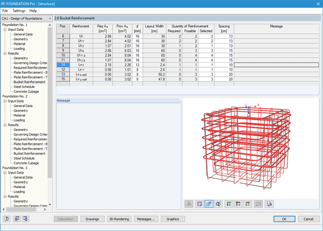
You can display the foundation in excellent rendering quality, including reinforcement. In the rendering, as well as in up to seven different dimensioned reinforcement drawings ready for construction, the module provides a solution proposal for bucket design. It is possible to modify the number, position, diameter, and spacing of used rebars here as well. You can also determine the shape of the applied links.
The dimensions of the foundation plate and bucket can be determined by the add-on module, or can be user-defined. Clearly arranged windows display the results of each performed design, including all intermediate values. They are covered in a reduced printout report providing a verifiable structural analysis.
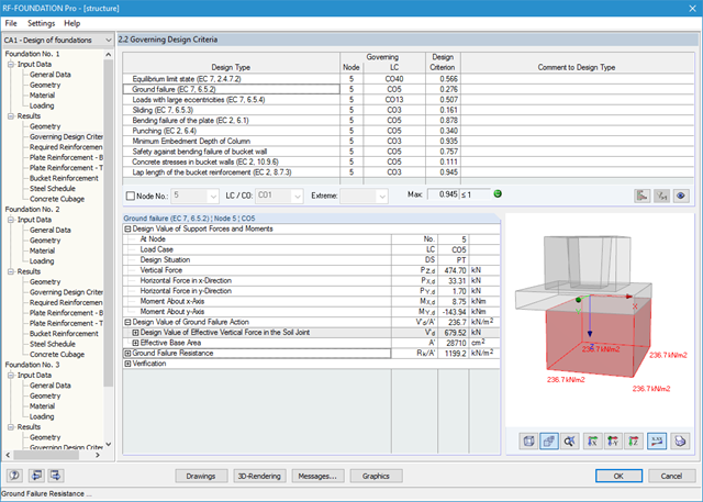
It is possible to perform the following designs:
- Equilibrium limit state design
- Uplift limit state design
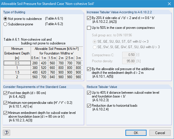
- Ground failure (soil contact pressure) design
- Strong eccentric loads design
- Design of foundation torsion and limitation of gaping joint
- Sliding design
- Settlement calculation
- Bending failure design of the plate and bucket
- Punching shear design
Foundation and bucket dimensions can be user-defined or determined by the module. You can edit the determined reinforcement manually. In this case, the designs are updated automatically.
.png?mw=640&hash=34966a7f3c34f6b7bb83003f1c13cb57a2f0cabb)
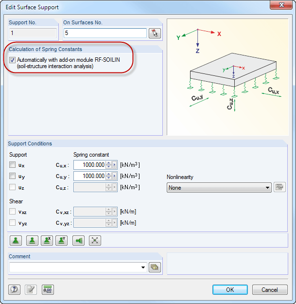
- Realistic representation of interaction between a building and soil
- Extensible library of soil properties
- Consideration of several soil samples (probes) at different locations, even outside the building
- Consideration of groundwater level as well as side effects due to excavation and lowest soil layer being solid
- Calculation of elastic foundation coefficients
- Determination and graphical display of stress diagrams and settlements in grid points