10 Wyniki
Wyświetl wyniki:
Sortuj według:
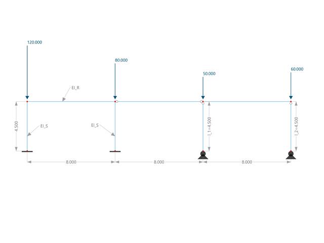
W tym przykładzie porównuje się długości efektywne i współczynnik obciążenia krytycznego, które mogą być obliczone w programie RFEM 6 przy użyciu rozszerzenia Stateczność konstrukcji, z obliczeniami ręcznymi. Układ konstrukcyjny stanowi sztywna rama z dwoma dodatkowymi słupami przegubowymi. Ten słup jest obciążany pionowymi obciążeniami skupionymi.

Konstrukcja składa się z swobodnie podpartej belki o przekroju dwuteowym. Obrót osiowy φx jest ograniczony na obu końcach, ale przekrój może ulec deplanacji (podpora widełkowa). Belka posiada początkową imperfekcję w kierunku Y zdefiniowaną jako krzywa paraboliczna o maksymalnym przemieszczeniu 30 mm w środku. Obciążenie równomierne zostaje przyłożone w środku górnego pasa profilu dwuteowego. Problem opisano za pomocą poniższego zestawu parametrów. Przykład obliczeniowy oparty jest na przykładzie wprowadzonym przez Gensichen i Lumpe.
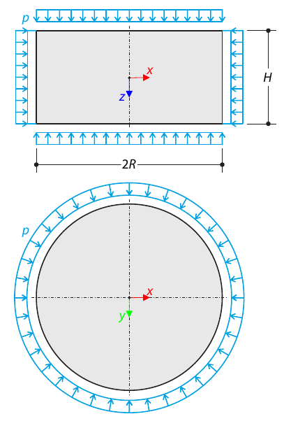
Walec wykonany z gruntu sprężysto-plastycznego jest poddawany trójosiowym warunkom testowym. Celem jest określenie granicznego naprężenia pionowego dla zniszczenia naprężenia od ścinania, pomijając ciężar własny. Uwzględniane jest początkowe naprężenie hydrostatyczne 100 kPa.
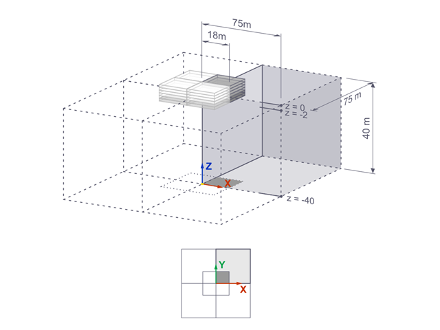
Osiadania sztywnego fundamentu kwadratowego na glinie jeziornej [1] są obliczane w programie RFEM. Modelowana jest jedna czwarta fundamentu. Fundament ma szerokość 75,0 m po obu stronach. Do wygenerowania wyników wykorzystywane są etapy budowy.
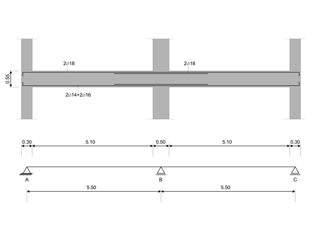
W tym przykładzie obliczeniowym obliczane są wartości nośności sił tnących na belkach zgodnie z EN 1998-1, 5.4.2.2 i 5.5.2.1 oraz nośność słupów przy zginaniu zgodnie z 5.2.3.3(2 ). System składa się z dwuprzęsłowej belki żelbetowej o rozpiętości 5,50 m. Belka jest częścią układu ramowego. Otrzymane wyniki są porównywane z wynikami w [1].
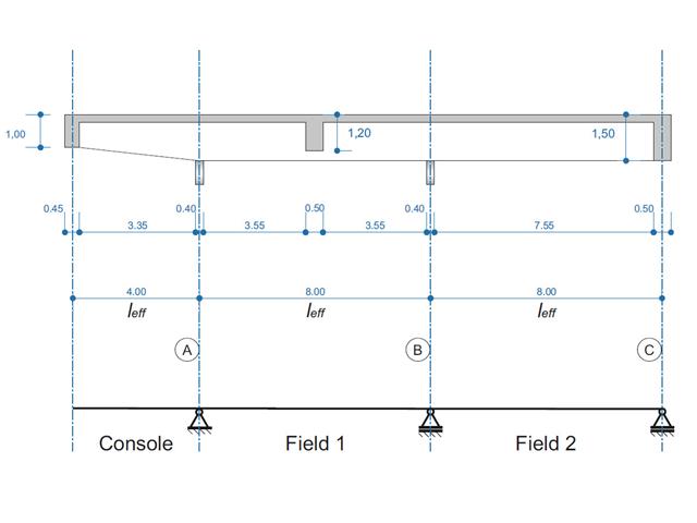
Belka żelbetowa została zaprojektowana jako belka dwuprzęsłowa na wsporniku. Przekrój zmienia się na całej długości wspornika (przekrój o zmiennym przekroju). Obliczane są siły wewnętrzne oraz wymagane zbrojenie podłużne i zbrojenie na ścinanie dla stanu granicznego nośności.
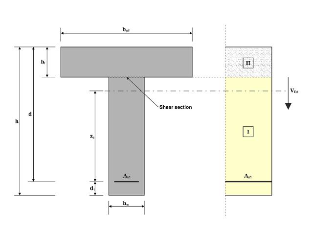
W tym przykładzie ścinanie na granicy między betonem wylanym w różnym czasie a odpowiednim zbrojeniem jest określane zgodnie z DIN EN 1992-1-1. Wyniki uzyskane w programie RFEM 6 zostaną porównane z poniższymi obliczeniami ręcznymi.
Model oparty jest na przykładzie 4 z [1]: Płyta podparta punktowo. Siły wewnętrzne i wymagane zbrojenie podłużne można znaleźć w przykładzie weryfikacji 1022. W tym przykładzie przebijanie jest rozpatrywane w osi B/2.
Model oparty jest na przykładzie 4 z [1]: Płyta podparta punktowo.
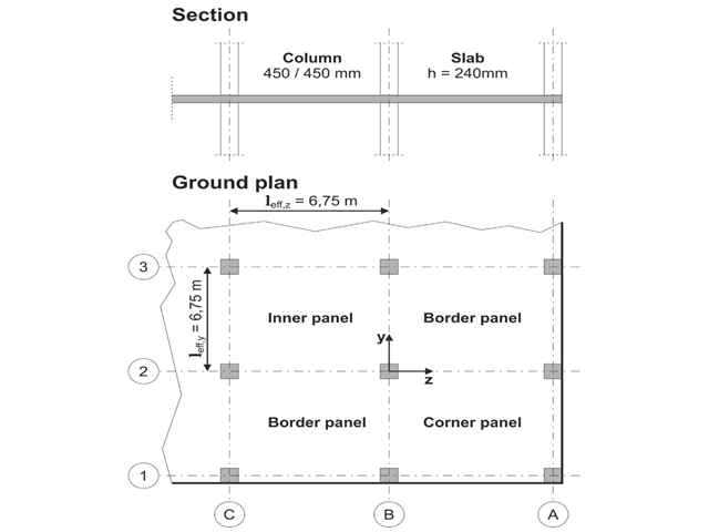
Należy zaprojektować płaską płytę budynku biurowego o wrażliwych na zarysowania ścianach lekkich. Należy zbadać panele wewnętrzne, brzegowe i narożne. Słupy i płyta są połączone monolitycznie. Słupy skrajne i narożne są zlicowane z krawędzią płyty. Osie słupów tworzą siatkę kwadratową. Jest to układ sztywny (budynek usztywniony ścianami usztywniającymi).
Budynek biurowy ma 5 kondygnacji i ma wysokość 3.000 m. Warunki środowiskowe, które należy przyjąć, określane są jako „zamknięte przestrzenie wewnętrzne”. Występują głównie oddziaływania statyczne.
Celem tego przykładu jest określenie momentów w płycie i wymaganego zbrojenia nad słupami przy pełnym obciążeniu.
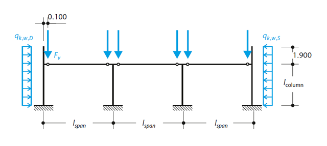
Zgodnie z DIN EN 1992-1-1/NA/A1:2015, na podstawie 1990-1-1/NA/A1:2012-08 słup z betonu zbrojonego jest projektowany pod kątem SGN w temperaturze normalnej. W obliczeniach zastosowano metodę krzywizny nominalnej; patrz DIN EN 1992-1-1, rozdział 5.8.8. Zaadresowany słup znajduje się na krawędzi trzyprzęsłowej konstrukcji ramowej, która składa się z 4 słupów wspornikowych i 3 pojedynczych kratownic połączonych przegubowo z nimi. Na słup działa siła pionowa prefabrykowanej kratownicy, śnieg i wiatr. Wyniki porównano z literaturą.