16 Wyniki
Wyświetl wyniki:
Sortuj według:

Zaplanowano dach z określoną geometrią zawartą w projekcie na dużych powierzchniach w połączeniu z zaawansowanymi metodami RFEM 6 i RFEM 6, które zostały zaprojektowane ręcznie. Został wprowadzony 3 Lastsysteme untersucht.
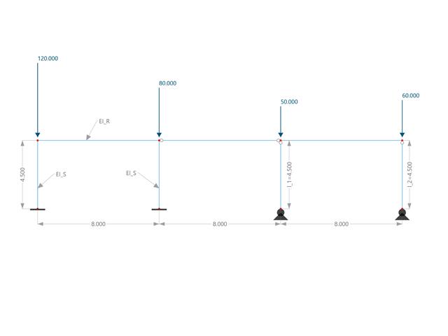
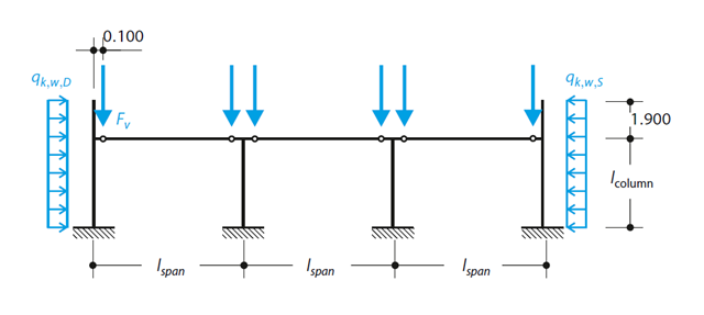
W tym przykładzie porównuje się długości efektywne i współczynnik obciążenia krytycznego, które mogą być obliczone w programie RFEM 6 przy użyciu rozszerzenia Stateczność konstrukcji, z obliczeniami ręcznymi. Układ konstrukcyjny stanowi sztywna rama z dwoma dodatkowymi słupami przegubowymi. Ten słup jest obciążany pionowymi obciążeniami skupionymi.
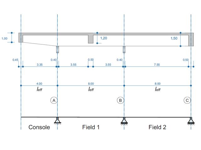
Belka żelbetowa została zaprojektowana jako belka dwuprzęsłowa na wsporniku. Przekrój zmienia się na całej długości wspornika (przekrój o zmiennym przekroju). Obliczane są siły wewnętrzne oraz wymagane zbrojenie podłużne i zbrojenie na ścinanie dla stanu granicznego nośności.
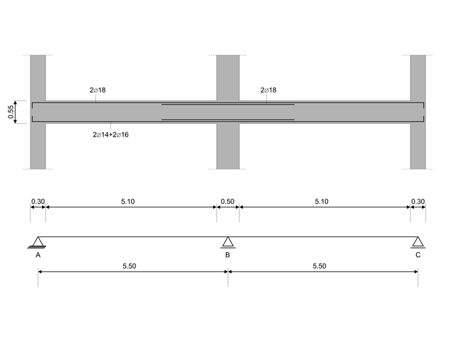
W tym przykładzie obliczeniowym obliczane są wartości nośności sił tnących na belkach zgodnie z EN 1998-1, 5.4.2.2 i 5.5.2.1 oraz nośność słupów przy zginaniu zgodnie z 5.2.3.3(2 ). System składa się z dwuprzęsłowej belki żelbetowej o rozpiętości 5,50 m. Belka jest częścią układu ramowego. Otrzymane wyniki są porównywane z wynikami w [1].
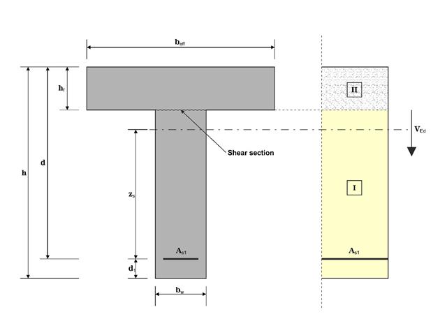
W tym przykładzie ścinanie na granicy między betonem wylanym w różnym czasie a odpowiednim zbrojeniem jest określane zgodnie z DIN EN 1992-1-1. Wyniki uzyskane w programie RFEM 6 zostaną porównane z poniższymi obliczeniami ręcznymi.
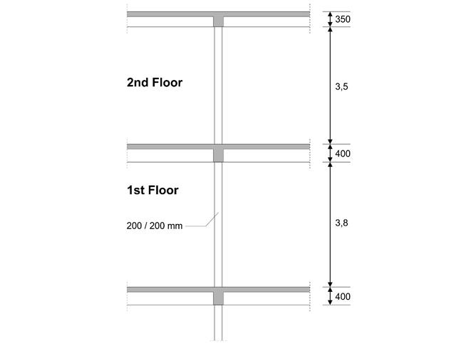
W pierwszym piętrze budynku zaprojektowano słup wewnętrzny. Słup jest monolityczny, połączony z belką górną i dolną. Uproszczona metoda A obliczeń odporności ogniowej dla słupów zgodnie z EC2-1-2 została potwierdzona, a wyniki porównane z [1].
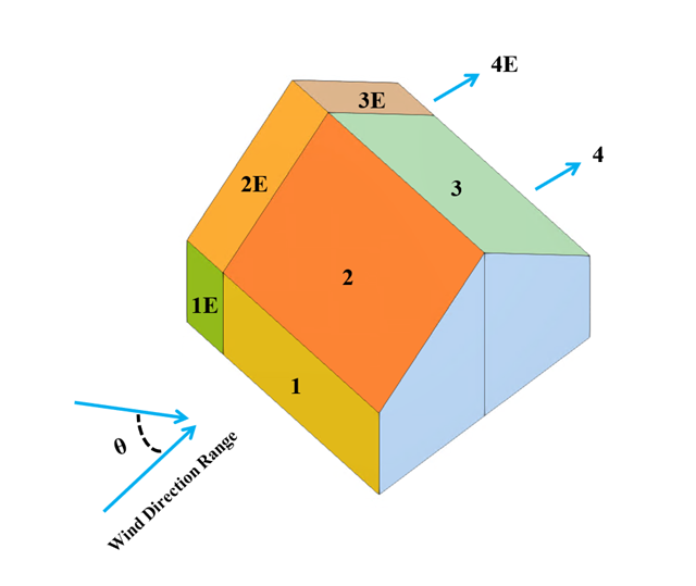
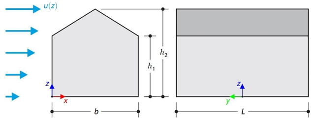
W bieżącym przykładzie walidacyjnym badany jest współczynnik ciśnienia wiatru (Cp) zarówno dla głównych elementów konstrukcyjnych (Cp,ave ), jak i drugorzędnych elementów konstrukcyjnych, takich jak systemy okładziny lub fasady (Cp,local ) w oparciu o NBC 2020 [1] and Baza danych japońskich tuneli aerodynamicznych dla niskiego budynku o nachyleniu 45 stopni. Zalecane ustawienie dla trójwymiarowego dachu płaskiego z ostrym okapem zostanie opisane w następnej części.
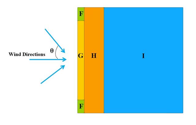
W poniższym przykładzie sprawdzamy wartość ciśnienia wiatru zarówno dla ogólnego projektowania konstrukcyjnego (Cp,10 ), jak i lokalnego projektowania konstrukcyjnego, takiego jak okładziny lub fasady (Cp,1 ) w oparciu o EN 1991-1-4, przykład dachu płaskiego [1] and Baza danych japońskich tuneli aerodynamicznych . Zalecane ustawienie dla trójwymiarowego dachu płaskiego z ostrym okapem zostanie opisane w następnej części.
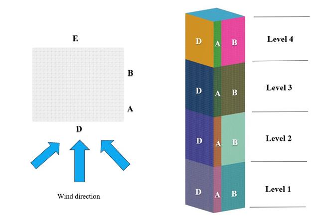
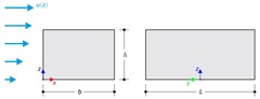
W bieżącym przykładzie walidacji badamy wartość parcia wiatru dla obu ogólnych projektów konstrukcyjnych (Cp,10 ) i okładzin lub elewacji (Cp,1 ) budynków na planie prostokąta zgodnie z EN 1991-1-4 [1]. Istnieją przypadki trójwymiarowe, o których więcej wyjaśnimy w następnej części.
Zgodnie z DIN EN 1992-1-1/NA/A1:2015, na podstawie 1990-1-1/NA/A1:2012-08 słup z betonu zbrojonego jest projektowany pod kątem SGN w temperaturze normalnej. W obliczeniach zastosowano metodę krzywizny nominalnej; patrz DIN EN 1992-1-1, rozdział 5.8.8. Zaadresowany słup znajduje się na krawędzi trzyprzęsłowej konstrukcji ramowej, która składa się z 4 słupów wspornikowych i 3 pojedynczych kratownic połączonych przegubowo z nimi. Na słup działa siła pionowa prefabrykowanej kratownicy, śnieg i wiatr. Wyniki porównano z literaturą.
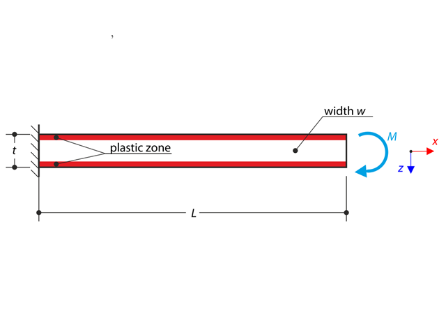
Wspornik jest w pełni utwierdzony na lewym końcu i obciążony momentem zginającym. W obliczeniach uwzględniono materiał plastyczny.
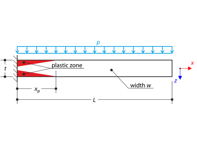
Cienka płyta jest w pełni utwierdzona na lewym końcu i obciążona równomiernym ciśnieniem. W obliczeniach uwzględniono materiał plastyczny.
Ten przykład weryfikacyjny porównuje obliczenia obciążenia wiatrem budynku z dachem dwuspadowym, z wykorzystaniem normy ASCE 7-16, z symulacją CFD w RWIND Simulation. The building is defined according to the sketch and the inflow velocity profile taken from the ASCE 7-16 standard.
Ten przykład weryfikacyjny porównuje obliczenia obciążenia wiatrem budynku z dachem płaskim, przeprowadzone w normie ASCE 7-16, z wykorzystaniem symulacji CFD w RWIND Simulation. The building is defined according to the sketch and the inflow velocity profile taken from the ASCE 7-16 standard.
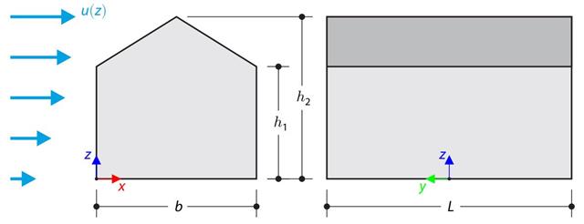
W przykładzie obliczeniowym porównano obliczenia obciążenia wiatrem budynku z dachem dwuspadowym, przeprowadzone zgodnie z normą EN 1991-1-4, z wykorzystaniem symulacji CFD w RWIND Simulation. The building is defined according to the sketch, and the inflow velocity profile is taken according to the standard EN 1991-1-4.
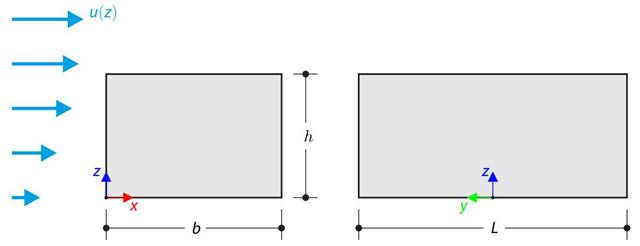
W przykładzie obliczeniowym porównano obliczenia obciążenia wiatrem budynku z płaskim dachem zgodnie z normą EN 1991-1-4 z wykorzystaniem symulacji CFD w RWIND Simulation. The building is defined according to the sketch, and the inflow velocity profile is taken according to the standard EN 1991-1-4.