18 Wyniki
Wyświetl wyniki:
Sortuj według:

W rozszerzeniu Projektowanie konstrukcji stalowych dla programu RFEM 6 dostępne są trzy typy ram sprężystych (zwykłe, pośrednie i specjalne). Wyniki obliczeń sejsmicznych zgodnie z AISC 341-22 są podzielone na dwie sekcje: wymagania dotyczące prętów i połączeń.

Rozszerzenie Projektowanie konstrukcji stalowych w RFEM 6 oferuje teraz możliwość przeprowadzania obliczeń sejsmicznych zgodnie z AISC 341-16 i AISC 341-22. Obecnie dostępnych jest pięć typów systemów sejsmicznych (SFRS).

W rozszerzeniu Projektowanie konstrukcji stalowych dla programu RFEM 6 dostępne są trzy typy ram sprężystych (zwykłe, pośrednie i specjalne). Wyniki obliczeń sejsmicznych zgodnie z AISC 341-16 są podzielone na dwie sekcje: wymagania dotyczące prętów i połączeń.

Obliczanie ramy momentowej zgodnie z AISC 341-16 jest teraz możliwe w rozszerzeniu Projektowanie konstrukcji stalowych dla programu RFEM 6. Wynik obliczeń sejsmicznych jest podzielony na dwie sekcje: wymagania dotyczące prętów i połączeń. W tym artykule omówiono wymaganą wytrzymałość połączenia. Przedstawiono przykładowe porównanie wyników pomiędzy RFEM a AISC Seismic Design Manual.

Obliczenia zwykłej ramy stężonej koncentrycznie (OCBF) oraz SCBF (specjalnej konstrukcji szkieletowej stężonej koncentrycznie) można przeprowadzić w rozszerzeniu Projektowanie konstrukcji stalowych dla programu RFEM 6. Wyniki obliczeń sejsmicznych zgodnie z AISC 341-16 i 341-22 są podzielone na dwie sekcje: Wymagania dotyczące prętów i połączeń.

Zarówno analiza drgań własnych, jak i analiza spektrum odpowiedzi przeprowadzane są na układzie liniowym. Jeżeli w modelu występują nieliniowości, podlega on linearyzacji, dzięki czemu elementy nieliniowe nie są brane pod uwagę w dalszej analizie. Mogą to być na przykład pręty rozciągane, podpory nieliniowe lub przeguby nieliniowe. W tym artykule pokazano, w jaki sposób można nimi zarządzać w analizie dynamicznej.
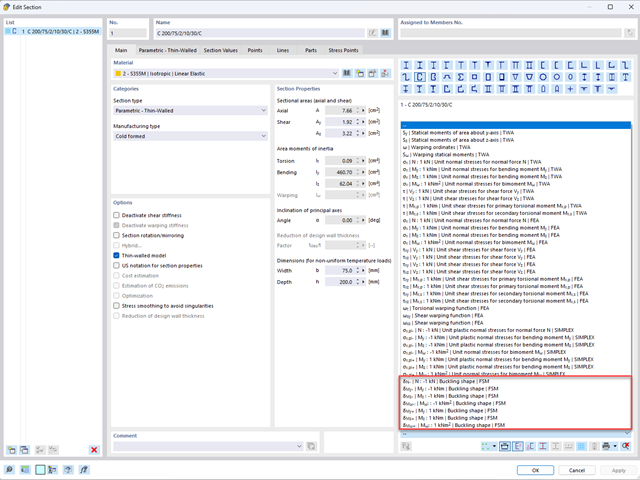
Aby umożliwić ocenę wpływu lokalnych zjawisk stateczności smukłych elementów, w programach RFEM 6 i RSTAB 9 można przeprowadzić liniową analizę obciążenia krytycznego na poziomie przekroju. Poniższy artykuł poświęcony jest podstawom obliczeń i interpretacji wyników.

Wymiarowanie prętów stalowych formowanych na zimno zgodnie z AISI S100-16 jest teraz dostępne w programie RFEM 6. Design can be accessed by selecting “AISC 360” as the standard in the Steel Design add-on. “AISI S100” is then automatically selected for the cold-formed design (Image 01).

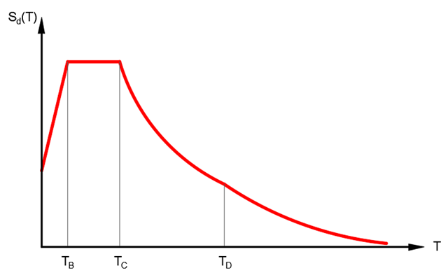
Analiza modalna jest punktem wyjścia do analizy dynamicznej układów konstrukcyjnych. Można ją wykorzystać do określenia wartości drgań własnych, takich jak częstotliwości drgań własnych, kształty drgań własnych, masy modalne i efektywne współczynniki masy modalnej. Wynik ten może zostać wykorzystany do obliczeń drgań oraz do dalszych analiz dynamicznych (na przykład obciążenia widmem odpowiedzi).

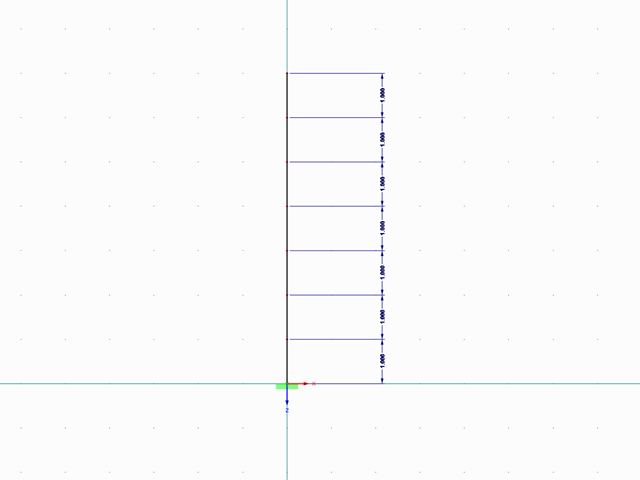
Sprawdzenie stateczności dla wymiarowania prętów zastępczych zgodnie z EN 1993-1-1, AISC 360, CSA S16 i innymi normami międzynarodowymi wymaga uwzględnienia długości obliczeniowej (tj. efektywnej długości prętów). W programie RFEM 6 długość efektywną można określić ręcznie, przypisując podpory węzłowe i współczynniki długości efektywnej lub, z drugiej strony, poprzez import z analizy stateczności. Obie opcje zostaną przedstawione w tym artykule poprzez określenie efektywnej długości słupa obramowanego na rysunku 1.
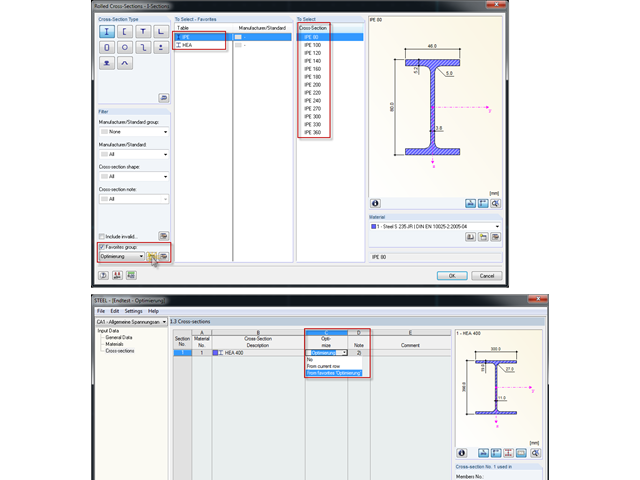
Bei der Querschnittsoptimierung in den Zusatzmodulen können auch beliebig definierte Querschnitts-Favoritenlisten ausgewählt werden - zusätzlich zu den Profilen aus der gleichen Profilreihe wie das ursprüngliche Profil.
Mit RF-/DYNAM Pro Ersatzlasten ist es möglich, eine Ersatzlastberechnung anhand des multimodalen Antwortspektren-Verfahrens zu durchzuführen. Im dargestellten Beispiel wurde dies für einen Mehrmassenschwinger durchgeführt.
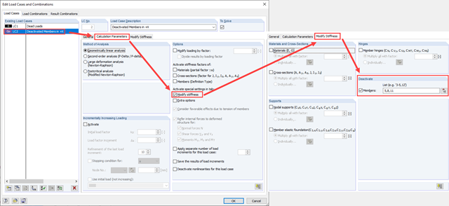
Zarówno analiza drgań własnych, jak i analiza spektrum odpowiedzi przeprowadzane są na układzie liniowym. Jeżeli w modelu występują nieliniowości, podlega on linearyzacji, dzięki czemu elementy nieliniowe nie są brane pod uwagę w dalszej analizie. W praktyce jednak bardzo często wprowadzamy do modeli elementy "tylko rozciągane". W przedstawionym artykule opisano, w jaki sposób można je poprawnie zastąpić dla przeprowadzenia liniowej analizy dynamicznej.
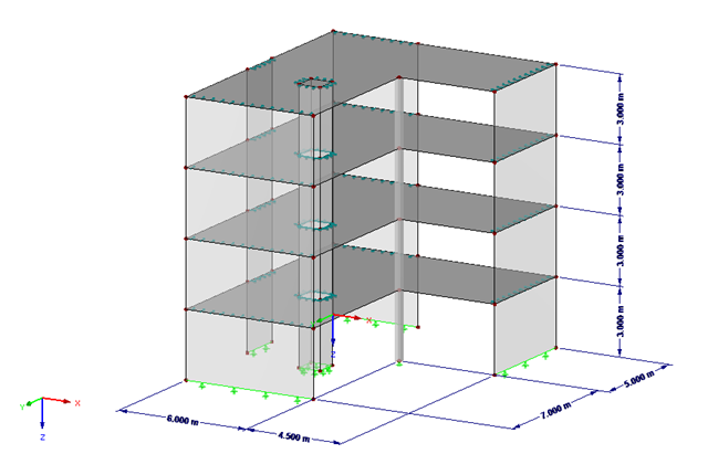
Podczas wprowadzania i przenoszenia obciążeń poziomych, takich jak wiatr lub obciążenia sejsmiczne, w modelach 3D pojawiają się coraz większe trudności. Aby uniknąć takich problemów, niektóre normy (np. ASCE 7, NBC) wymagają uproszczenia modelu za pomocą przepon, które rozkładają obciążenia poziome na elementy konstrukcyjne przenoszące obciążenia, ale nie mogą samodzielnie przenosić zginania (tzw. „Przepona”).
Poniższy artykuł opisuje sposób przeprowadzania obliczeń belki dwuprzęsłowej, poddanej zginaniu, z zastosowaniem modułu dodatkowego RF-/STEEL EC3 zgodnie z EN 1993-1-1. Globalne zakłócenie stateczności zostanie wykluczone, dzięki zastosowaniu dostatecznych środków zapewniających stateczność.
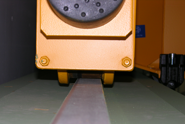
Bei Kranbahnen mit großen Stützweiten ist nicht selten die Horizontallast aus Schräglauf bemessungsrelevant. In diesem Beitrag sollen die Entstehung dieser Kräfte und die richtige Eingabe in KRANBAHN beschrieben werden. Es wird hierbei auf die praktische Ausführung und den theoretischen Hintergrund eingegangen.
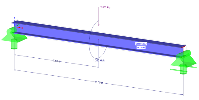
Anhand eines Verifikationsbeispiels soll die Bemessung eines torsionsbeanspruchten Trägers nach AISC Design Guide 9 gezeigt werden. Die Bemessung erfolgt mit dem Zusatzmodul RF-STAHL AISC und der Modulerweiterung RF-STAHL Wölbkrafttorsion mit sieben Freiheitsgraden.
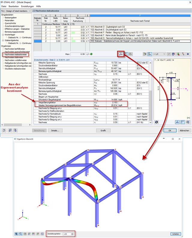
Po przeprowadzeniu analizy w module RF-/STEEL AISC, postacie drgań dla zbiorów prętów można wyświetlić graficznie w osobnym oknie. Select the relevant set of members in the result window and click the [Mode Shapes] button.