10 Wyniki
Wyświetl wyniki:
Sortuj według:

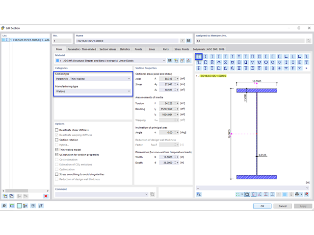
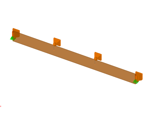
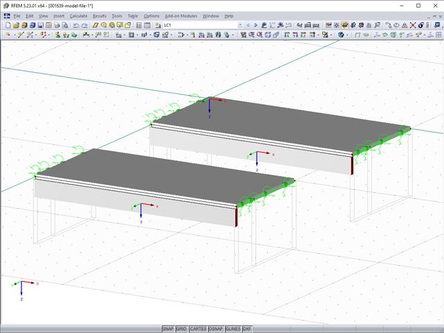
Blachownica to ekonomiczny wybór w przypadku konstrukcji o dużych rozpiętościach. I-section steel plate girder typically has a deep web to maximize its shear capacity and flange separation, yet thin web to minimize the self-weight. Due to its large height-to-thickness (h/tw) ratio, transverse stiffeners may be required to stiffen the slender web.

W rozszerzeniu Projektowanie konstrukcji stalowych dla programu RFEM 6 dostępne są trzy typy ram sprężystych (zwykłe, pośrednie i specjalne). Wyniki obliczeń sejsmicznych zgodnie z AISC 341-22 są podzielone na dwie sekcje: wymagania dotyczące prętów i połączeń.

W rozszerzeniu Projektowanie konstrukcji stalowych dla programu RFEM 6 dostępne są trzy typy ram sprężystych (zwykłe, pośrednie i specjalne). Wyniki obliczeń sejsmicznych zgodnie z AISC 341-16 są podzielone na dwie sekcje: wymagania dotyczące prętów i połączeń.
Blachownica to ekonomiczny wybór w przypadku konstrukcji o dużych rozpiętościach. I-section steel plate girder typically has a deep web to maximize its shear capacity and flange separation, yet thin web to minimize the self-weight. Due to its large height-to-thickness (h/tw) ratio, transverse stiffeners may be required to stiffen the slender web.
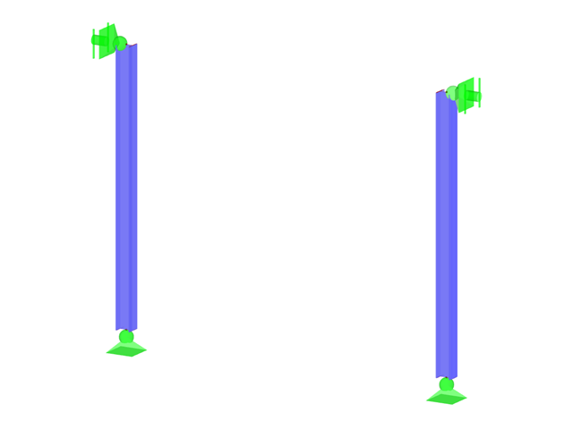
W przypadku analizy stateczności prętów przy użyciu metody pręta zastępczego konieczne jest zdefiniowanie długości wyboczeniowej lub zwichrzenia w celu określenia obciążenia krytycznego dla utraty stateczności. W tym artykule przedstawiono funkcję specyficzną dla programu RFEM 6, za pomocą której można przypisać mimośród do podpór węzłowych, a tym samym wpłynąć na określenie krytycznego momentu zginającego uwzględnianego w analizie stateczności.
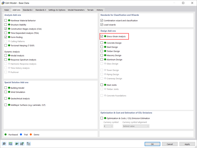
W tym artykule pokazano, jak zarządzać danymi wejściowymi dla konfiguracji obliczeń prętów i powierzchni w rozszerzeniu Analiza naprężeniowo-odkształceniowa.

Dzięki rozszerzeniu Połączenia stalowe dla RFEM 6 można tworzyć i analizować połączenia stalowe przy użyciu wydzielonego modelu ES. Modelowanie połączeń można kontrolować poprzez proste i wygodne wprowadzanie elementów. Elementy stalowego połączenia można definiować ręcznie lub przy użyciu szablonów dostępnych w bibliotece. Pierwsza metoda została opisana w poprzednim artykule z Bazy wiedzy zatytułowanym „Nowe podejście do wymiarowania połączeń stalowych w programie RFEM 6”. W tym artykule skupimy się na tej drugiej metodzie; tzn. pokaże, jak definiować komponenty połączenia stalowego przy użyciu szablonów dostępnych w bibliotece programu.
Czasami konstrukcja wymaga zbrojenia w przypadku dodawania nowego stropu lub w przypadku, gdy istniejący pręt okazuje się być poddany trudnym do przewidzenia obciążeniom. W wielu przypadkach nie ma możliwości łatwej wymiany elementu konstrukcji, a wówczas konieczne jest zastosowanie wzmocnienia zdolnego do przeniesienia nowych obciążeń.
Jeżeli żebro w stropie jest elementem konstrukcji obliczanej nieliniowo lub jest sztywno zamocowane w ścianach dochodzących, do jego modelowania należy użyć powierzchni zamiast pręta. Aby żebro nadal mogło być zaprojektowane jako element prętowy, należy zdefiniować belkę wynikową o prawidłowym mimośrodzie, która pozwala odczytać siły wewnętrzne w powłoce jako siły wewnętrzne dla równoważnego pręta.
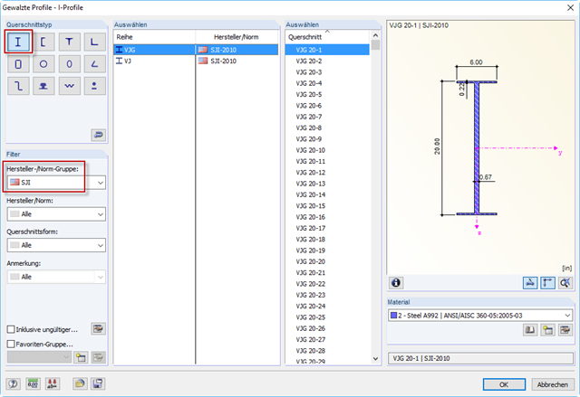
The Steel Joist Institute (SJI) previously developed Virtual Joist tables to estimate the section properties for Open Web Steel Joists. These Virtual Joist sections are characterized as equivalent wide-flange beams which closely approximate the joist chord area, effective moment of inertia, and weight. Virtual Joists are also available in the RFEM and RSTAB cross-section database.