15 Wyniki
Wyświetl wyniki:
Sortuj według:

Wymiarowanie prętów stalowych formowanych na zimno zgodnie z AISI S100-16/CSA S136-16 jest dostępne w RFEM 6. Dostęp do obliczeń można uzyskać, wybierając normy „AISC 360” lub „CSA S16” w rozszerzeniu Projektowanie konstrukcji stalowych. Następnie dla obliczeń elementów formowanych na zimno automatycznie wybierane jest „AISI S100” lub „CSA S136”.
Do obliczania sprężystego obciążenia wyboczeniowego pręta program RFEM stosuje metodę DSM. Bezpośrednia metoda wytrzymałości oferuje dwa typy rozwiązań, numeryczne (metoda pasm skończonych) i analityczne (specyfikacja). Krzywą charakterystyczną (sygnaturę) FSM i kształty wyboczenia można wyświetlić w oknie dialogowym Przekroje.
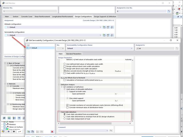
W konfiguracji stanu granicznego użytkowalności można dostosowywać różne parametry obliczeniowe przekrojów. W tym miejscu można kontrolować warunek przekroju zastosowany do analizy odkształcenia i szerokości zarysowania.
Można aktywować następujące ustawienia:
- Stan zarysowania obliczony na podstawie powiązanego obciążenia
- Stan zarysowany obliczony jako obwiednia ze wszystkich sytuacji obliczeniowych SGU
- Stan przekroju zarysowanego - niezależny od obciążenia
- 002089
- Ogólne informacje
- Skręcanie skrępowane (7 stopni swobody) RFEM 6
- Skręcanie skrępowane (7 stopni swobody) RSTAB 9
- Uwzględnienie 7 lokalnych kierunków deformacji (ux , uy, uz, φx, φy, φz, ω ) lub 8 sił wewnętrznych (N , Vu, Vv, Mt, pri, Mt, s, Mu, Mv, Mω ) przy obliczaniu elementów prętowych
- Możliwość stosowania w połączeniu z analizą statyczno-wytrzymałościową według teorii II rzędu, i analiza dużych deformacji (można również uwzględnić imperfekcje)
- W połączeniu z rozszerzeniem Analiza stateczności umożliwia definiowanie współczynników obciążenia krytycznego i kształtów drgań dla problemów stateczności, takich jak wyboczenie skrętne i zwichrzenie
- Uwzględnianie blach czołowych i usztywnień poprzecznych jako sprężystości skrępowanej podczas obliczania przekrojów dwuteowych z automatycznym określaniem i wyświetlaniem graficznym sztywności sprężystości deplanacyjnej
- Graficzne przedstawienie deplanacji przekroju prętów w stanie odkształcenia
- Pełna integracja z RFEM i RSTAB

- 002090
- Ogólne informacje
- Skręcanie skrępowane (7 stopni swobody) RFEM 6
- Skręcanie skrępowane (7 stopni swobody) RSTAB 9
Obliczenia skręcania skrępowanego można przeprowadzić dla całego układu. Uwzględniasz zatem dodatkową wartość 7 stopnia swobody w obliczeniach pręta. Sztywności połączonych elementów konstrukcyjnych są uwzględniane automatycznie. Oznacza to, że nie ma potrzeby' definiowania równoważnych sztywności sprężystych ani warunków podparcia dla układu odłączanego.
Następnie można wykorzystać siły wewnętrzne z obliczeń ze skręcaniem skrępowanym w rozszerzeniu do obliczeń. W zależności od materiału i wybranej normy należy uwzględnić bimoment wyboczeniowy i drugorzędny moment skręcający. Typowym zastosowaniem jest analiza stateczności według teorii drugiego rzędu z wykorzystaniem imperfekcji w konstrukcjach stalowych.
Czy wiecie, że...? Zastosowanie nie ogranicza się do przekrojów stalowych cienkościennych. Pozwala to na przykład na przeprowadzenie obliczeń idealnego momentu krytycznego dla belek o przekrojach z drewna litego.

- 002401
- Ogólne informacje
- Skręcanie skrępowane (7 stopni swobody) RFEM 6
- Skręcanie skrępowane (7 stopni swobody) RSTAB 9
- Funkcję skręcania skrępowanego można aktywować lub dezaktywować w zakładce Rozszerzenia w Danych podstawowych modelu.
- Po aktywowaniu rozszerzenia interfejs użytkownika w programie RFEM zostaje rozszerzony o nowe wpisy w nawigatorze, tabelach i oknach dialogowych.
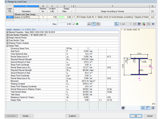
Dzięki zintegrowanemu rozszerzeniu modułu RF-/STEEL Warping Torsion, możliwe jest przeprowadzenie obliczeń zgodnie z Design Guide 9 w RF-/STEEL AISC.
Obliczenia są przeprowadzane z 7 stopniami swobody zgodnie z teorią skręcania skrępowanego i umożliwiają realistyczne obliczenia stateczności z uwzględnieniem skręcania.
Definiowanie krytycznego momentu wyboczeniowego odbywa się w module RF-/STEEL AISC za pomocą solwera wartości własnych, który umożliwia dokładne określenie krytycznego obciążenia wyboczeniowego.
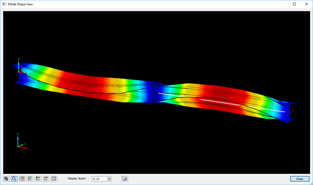
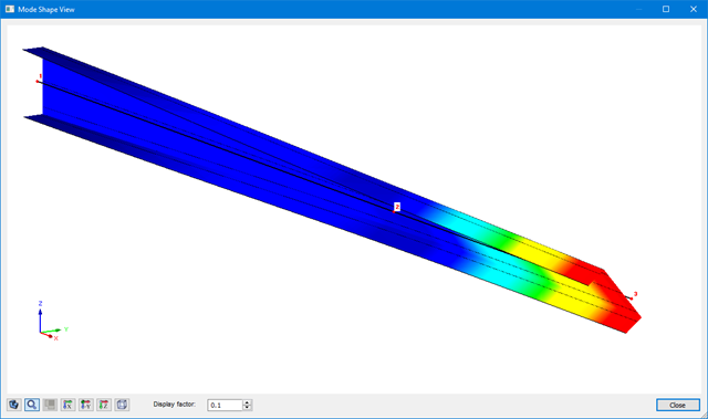
Solwer wartości własnych pokazuje okno z grafiką wartości własnych, które umożliwia sprawdzenie warunków brzegowych.
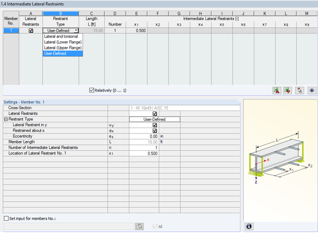
W programie STEEL AISC możliwe jest uwzględnienie pośrednich podpór bocznych w dowolnym miejscu. Na przykład, możliwa jest stabilizacja tylko górnej półki.
Ponadto można przypisać boczne podpory pośrednie zdefiniowane przez użytkownika; na przykład pojedyncze sprężyny obrotowe i sprężyny translacyjne w dowolnym miejscu przekroju.
- Stosuje się do prętów zdefiniowanych jako zbiory prętów
- Oddzielny solwer uwzględniający 7 kierunków deformacji (ux , uy, uz, φx, φy, φz, ω ) lub 8 sił wewnętrznych (N, Vu, Vv, Mt, pri, Mt, s, Mu, Mv,M )
- Projektowanie nieliniowe według analizy drugiego rzędu
- Wprowadzanie imperfekcji
- Obliczanie współczynników obciążenia krytycznego i postaci wyboczenia oraz ich wizualizacja (wraz z skręcaniem skrępowanym)
- Integracja z wymiarowaniem prętów w modułach dodatkowych RF-/STEEL AISC i RF-/STEEL EC3
- Dostępne dla wszystkich przekrojów stalowych cienkościennych
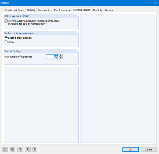
Ponieważ moduł RF-/STEEL Warping Torsion jest w pełni zintegrowany z modułami RF-/STEEL AISC i RF‑/STEEL EC3, dane są wprowadzane w taki sam sposób, jak w przypadku obliczeń w tych modułach. W oknie dialogowym Szczegóły, zakładka Skręcanie skrępowane (patrz rysunek po prawej stronie), konieczne jest tylko zaznaczenie opcji "Przeprowadzić analizę skręcania skrępowanego". W tym oknie dialogowym można również zdefiniować maksymalną liczbę iteracji.
Analiza skręcania skrępowanego jest przeprowadzana dla zbiorów prętów w modułach RF-/STEEL AISC i RF-/STEEL EC3. Można dla nich zdefiniować warunki brzegowe, takie jak podpory węzłowe lub zwolnienia na końcach prętów.
Możliwe jest również określenie imperfekcji do obliczeń nieliniowych.
RF-CONCRETE Surfaces (en)
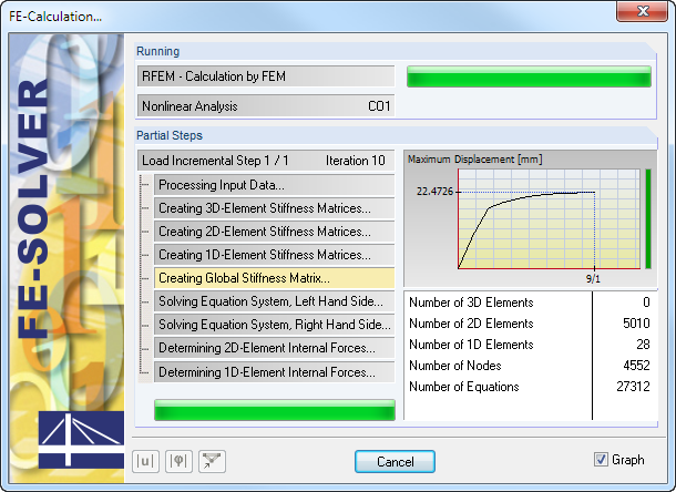
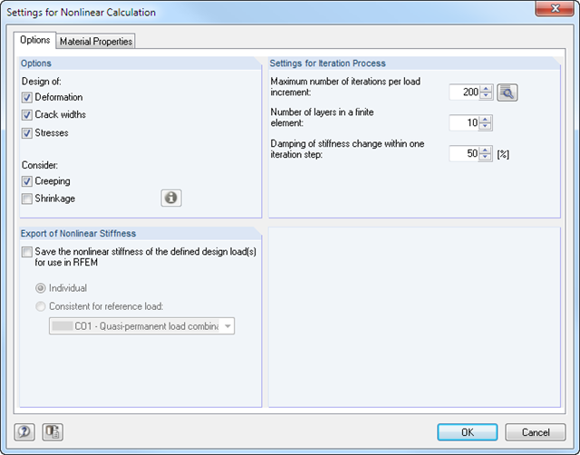
Obliczenia nieliniowe rozpoczyna się poprzez wybranie tej metody dla obliczeń w stanie granicznym użytkowalności. Różne typy analizy, a także wykresy odkształceń i naprężeń dla betonu oraz stali zbrojeniowej można wybrać indywidualnie. Na proces iteracji mogą mieć wpływ następujące parametry kontrolne: dokładność zbieżności, maksymalna liczba iteracji, rozmieszczenie warstw na wysokości przekroju oraz współczynnik tłumienia.
Wartości graniczne w stanie granicznym użytkowalności można ustawić indywidualnie dla każdej powierzchni lub grupy powierzchni. Jako dozwolone wartości graniczne można zdefiniować deformację maksymalną, naprężenia maksymalne oraz maksymalne szerokości rys. Podczas definiowania deformacji maksymalnej należy dodatkowo określić, czy do obliczeń ma zostać użyty układ odkształcony czy nieodkształcony.
RF-CONCRETE Members (en)
Obliczenia nieliniowe można zastosować do obliczeń stanu granicznego nośności i użytkowalności. Użytkownik może indywidualnie ustalać, w jaki sposób stosowane są wytrzymałość betonu na rozciąganie lub usztywnienie przy rozciąganiu. Na proces iteracji mogą wpływać następujące parametry kontrolne: dokładność zbieżności, maksymalna liczba iteracji i współczynnik tłumienia.
Wyniki analizy skręcania skrępowanego są wyświetlane w modułach RF-/STEEL AISC i RF-/STEEL EC3 w zwykły sposób. Odpowiednie okna wyników zawierają między innymi wartości krytycznego skręcania i skręcania, siły wewnętrzne oraz podsumowanie obliczeń.
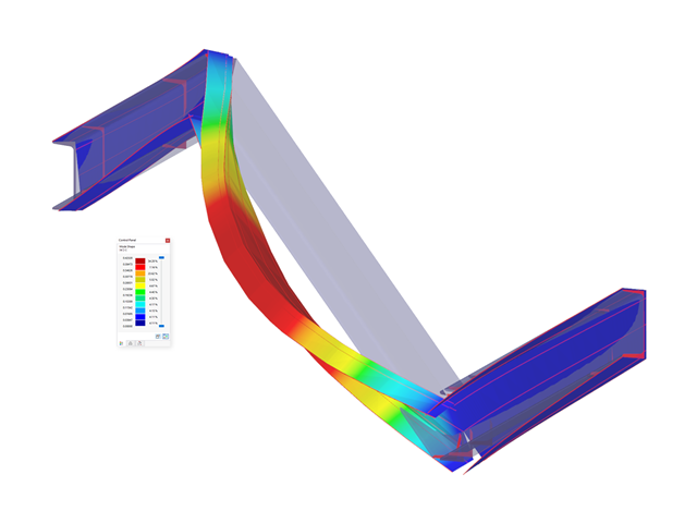
Graficzne przedstawienie postaci drgań (wraz z deplanacją) umożliwia realistyczną ocenę zachowania się wyboczenia.
RF-CONCRETE Surfaces:
Nieliniowa analiza deformacji jest przeprowadzana metodą iteracyjną, z uwzględnieniem sztywności w przekrojach zarysowanych i niezarysowanych. Nieliniowe modelowanie betonu zbrojonego wymaga zdefiniowania właściwości materiału, które różnią się w zależności od grubości powierzchni. Dlatego element skończony jest dzielony na określoną liczbę warstw stali i betonu w celu określenia wysokości przekroju.
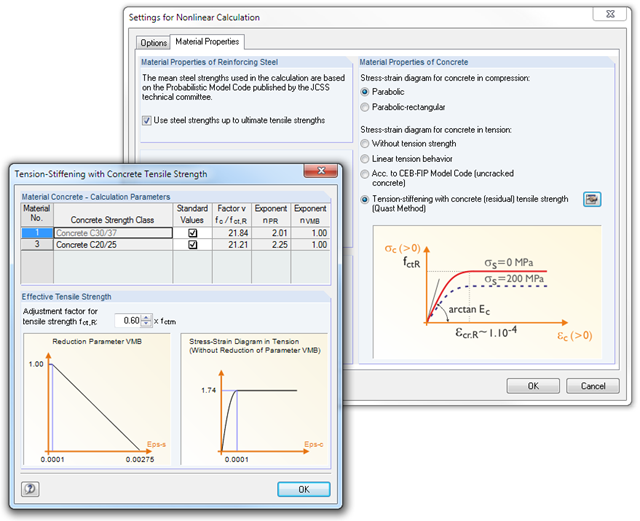
Średnie wytrzymałości stali zastosowane w obliczeniach oparte są na 'Normie modelu probabilistycznego', opublikowanym przez komitet techniczny JCSS. To od użytkownika zależy, czy wytrzymałość stali zostanie przyłożona do granicy wytrzymałości na rozciąganie (wzrost rozgałęzienia w obszarze plastycznym). W odniesieniu do właściwości materiałowych można kontrolować wykres naprężenie-odkształcenie dla wytrzymałości na ściskanie i rozciąganie. Jako wytrzymałość betonu na ściskanie można wybrać paraboliczny lub paraboliczno-prostokątny wykres naprężenie-odkształcenie. Po stronie rozciągania betonu istnieje możliwość dezaktywacji wytrzymałości na rozciąganie, a także zastosowania wykresu liniowo-sprężystego, wykresu zgodnie z normą modelu CEB-FIB 90:1993 oraz rezydualnej wytrzymałości betonu na rozciąganie z uwzględnieniem usztywnienia rozciąganego między rysami.
Ponadto można określić, które wartości wyników mają być wyświetlane po obliczeniach nieliniowych w stanie granicznym użytkowalności:
- Odkształcenia (globalne, lokalne dla układu niezdeformowanego/nieodkształconego)
- Szerokości, wysokości rys oraz rozstaw górnej i dolnej powierzchni w głównych kierunkach I oraz II
- Naprężenia w betonie (naprężenie i odkształcenie w głównym kierunku I i II) oraz w zbrojeniu (odkształcenie, pole przekroju, profil, otulina i kierunek w każdym kierunku zbrojenia)
RF-CONCRETE Members:
Nieliniowa analiza deformacji konstrukcji szkieletowych jest przeprowadzana metodą iteracyjną, uwzględniającą sztywność w przekrojach zarysowanych i niezarysowanych. Właściwości materiałowe betonu i stali zbrojeniowej wykorzystywane w obliczeniach nieliniowych są wybierane zgodnie ze stanem granicznym. Udział wytrzymałości betonu na rozciąganie pomiędzy rysami (wzmocnienie przy rozciąganiu) można określić za pomocą zmodyfikowanego wykresu naprężenie-odkształcenie stali zbrojeniowej lub poprzez zastosowanie rezydualnej wytrzymałości betonu na rozciąganie.
- Iteracyjne nieliniowe obliczanie deformacji dla konstrukcji belkowych i płytowych wykonanych z betonu zbrojonego poprzez określenie sztywności odpowiedniego elementu poddanego zdefiniowanym obciążeniom
- Analiza deformacji zarysowanych powierzchni żelbetowych (stan II)
- Ogólna nieliniowa analiza stateczności prętów ściskanych wykonanych z betonu zbrojonego; na przykład zgodnie z EN 1992-1-1, 5.8.6
- Usztywnienie przy rozciąganiu betonu między rysami
- Dostępne są liczne załączniki krajowe do obliczeń zgodnie z Eurokodem 2 (EN 1992-1-1:2004 + A1:2014, patrz EC2 dla RFEM)
- Opcjonalne uwzględnienie wpływów długotrwałych, takich jak pełzanie lub skurcz
- Nieliniowe obliczanie naprężeń w stali zbrojeniowej i betonie
- Nieliniowe obliczanie szerokości rys
- Elastyczność dzięki szczegółowym opcjom ustawień dla podstawy i zakresu obliczeń
- Graficzne przedstawienie wyników zintegrowane z RFEM; na przykład odkształcenie lub ugięcie płaskiej płyty wykonanej z betonu zbrojonego
- Przejrzyste zestawienie wyników w formie numerycznej w stosownych oknach oraz możliwość ich graficznego przedstawienia na konstrukcji
- Pełna integracja wyników z protokołem wydruku programu RFEM
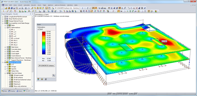
Po zakończeniu obliczeń, moduł wyświetla przejrzyście ułożone tabele zawierające wyniki obliczeń nieliniowych. Wszystkie wartości pośrednie są uwzględnione w sposób zrozumiały. Graficzne przedstawienie stopni wykorzystania, odkształceń, naprężeń w betonie i stali zbrojeniowej, szerokości i głębokości rys oraz odległości między rysami w programie RFEM ułatwia szybki przegląd obszarów krytycznych lub zarysowanych.
Komunikaty o błędach lub uwagi dotyczące obliczeń ułatwiają znajdowanie problemów obliczeniowych. Ponieważ wyniki obliczeń są wyświetlane według powierzchni lub punktów wraz ze wszystkimi wynikami pośrednimi, można odtworzyć wszystkie szczegóły obliczeń.
Dzięki opcjonalnemu eksportowi tabel danych wejściowych lub wyników do MS Excel, dane pozostają dostępne do wykorzystania w innych programach. Pełne zintegrowanie wyników z protokołem wydruku programu RFEM gwarantuje weryfikowalność wymiarowania konstrukcji.