56 Wyniki
Wyświetl wyniki:
Sortuj według:

- Proponowane połączenie można zastosować do wszystkich wybranych węzłów w konstrukcji
- Położenie połączenia można zdefiniować w zakładce 'Główne' okna dialogowego rozszerzenia
- Obliczenia są przeprowadzane dla wszystkich połączeń w konstrukcji, a po zakończeniu obliczeń wyniki mogą być wyświetlane we wszystkich połączeniach
- W tabeli wyświetlane są wyniki dla poszczególnych połączeń, każde połączenie jest obliczane i może być zapisane osobno

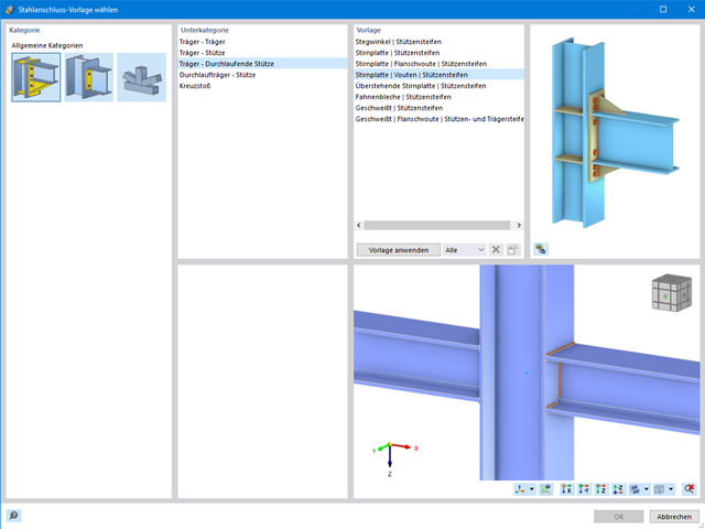
Złożone połączenie belek poziomych ze słupem oraz połączenie stężeń ukośnych
Model połączenia został zamodelowany przy użyciu około 50 komponentów. Model został stworzony na podstawie rzeczywistego przykładu wykorzystania w konstrukcji.
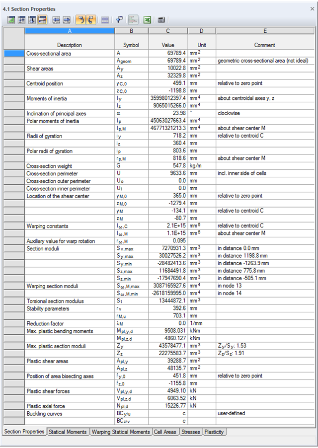
SHAPE-THIN określa charakterystyki przekroju i naprężenia dla przekrojów otwartych, zamkniętych, połączonych i niepołączonych.
- parametry przekroju
- Pole przekroju A
- Pole ścinane Ay, Az, Au i Av
- Położenie środka ciężkości yS, zS
- momenty pola 2 stopnie Iy, Iz, Iyz, Iu, Iv, Ip, Ip,M
- Promienie bezwładności iy, iz, iyz, iu, iv, ip, ip,M
- Nachylenie osi głównych α
- Ciężar przekroju G
- Średnica przekroju U
- momenty bezwładności przy skręcaniu stopnieIT , IT , IT,St.Venant, IT,Bredt, IT,s
- Położenie środka ścinania yM, zM
- Stałe deplanacji Iω,S, Iω,M or Iω,D dla utwierdzenia bocznego
- Max/min moduły przekroju Sy, Sz, Su, Sv, Sω,M z położeniami
- Promienie przekroju ru, rv, rM,u, rM,v
- Współczynnik redukcyjny λM
- Plastyczne charakterystyki przekroju
- Siła osiowa Npl,d
- Siły tnące Vpl,y,d, Vpl,z,d, Vpl,u,d, Vpl,v,d
- Momenty zginające Mpl,y,d, Mpl,z,d, Mpl,u,d, Mpl,v,d
- Moduły przekroju Zy, Zz, Zu, Zv
- Pola ścinania Apl,y, Apl,z, Apl,u, Apl,v
- Położenie osi powierzchni fu, fv,
- Wyświetlanie elipsy bezwładności
- Momenty statyczne pola Qu, Qv, Qy, Qz z położeniem maksimum i określeniem przebiegu ścinania
- Współrzędne wycinkowe ωM
- momenty bezwładności (wycinkowe powierzchnie) Sω,M
- Pola komórek Am zamkniętych przekrojów
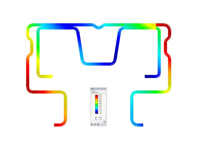
- Naprężenia normalne σx wywołane siłą osiową, momentem zginającym i bimomentem deplanacji
- Naprężenia styczne τ od sił tnących oraz pierwotnych i drugorzędnych momentów skręcających
- Naprężenia zastępcze σv ze współczynnikiem dla naprężeń ścinających, który można dostosować do własnych potrzeb
- Stopnie wykorzystania odniesione do naprężeń granicznych
- Naprężenia dla krawędzi lub osi elementu
- Naprężenia w spoinach pachwinowych
- Charakterystyki przekrojów niepołączonych (rdzeń budynku wysokościowego, przekroje złożone)
- Siły tnące wywołane zginaniem i skręcaniem
- Obliczanie nośności plastycznej z określeniem współczynnika zwiększającego αpl
- Sprawdzenie stosunków c/t według metody el-el, el-pl lub pl-pl wg DIN 18800

W przypadku przekrojów prostokątnych zwykle można uzyskać bezpośrednie połączenie za pomocą spoin. W ten sam sposób można je jednak połączyć z innymi przekrojami. Ponadto inne elementy, takie jak blachy czołowe, pomagają w łączeniu przekrojów prostokątnych z innymi elementami konstrukcyjnymi.

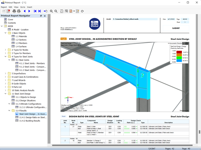
Stalowe połączenia śrubowe z blachami węzłowymi na konstrukcji zadaszenia.
Pobierz model do analizy statyczno-wytrzymałościowej i otwórz go w programie RFEM 6, korzystając z rozszerzenia Połączenia stalowe.
Główne funkcje wymiarowania połączeń są najpierw pogrupowane i wyświetlane wraz z podstawową geometrią połączenia w pierwszym oknie wyników. W pozostałych tabelach wyników można zobaczyć wszystkie istotne szczegóły obliczeń, takie jak nośność kotew, naprężenia w spoinach itp.
Wymiary, specyfikacje materiałowe i spoiny, które są istotne dla konstrukcji połączenia, są widoczne od razu i można je wydrukować. Połączenia można zwizualizować w module dodatkowym RF-/JOINTS Steel - Column Base lub w modelu RFEM/RSTAB.
Wszystkie grafiki mogą zostać dołączone do protokołu wydruku programu RFEM/RSTAB lub wydrukowane bezpośrednio. Dzięki skalowaniu wyników, możliwa jest optymalna kontrola wizualna już na etapie projektowania.

Rozszerzenie Połączenia stalowe umożliwia wymiarowanie połączeń prętów o złożonych przekrojach. Ponadto można przeprowadzać obliczenia połączeń dla prawie wszystkich przekrojów cienkościennych z biblioteki programu RFEM.
Przejdź do filmu
Wymiarowanie połączenia ramy o prętach zbieżnych i usztywnionych. Dla połączenia przeprowadzono analizę naprężeń i stateczności przy wyboczeniu. Aby wyświetlić wyniki dla wyboczenia, połączenie zostało przekształcone w osobny model.
Program wspiera Cię: Moduł określa siły w śrubach na podstawie modelu analitycznego ES i analizuje je automatycznie. Rozszerzenie przeprowadza obliczenia nośności śrub dla przypadków uszkodzeń, takich jak rozciąganie, ścinanie, docisk otworu i przebicie, zgodnie z normą i wyświetla w przejrzysty sposób wszystkie wymagane współczynniki.
Chcesz przeprowadzić wymiarowanie spoin? Spoiny są modelowane jako sprężysto-plastyczne elementy powierzchniowe, a ich naprężenia są odczytywane z modelu analitycznego ES. Kryterium plastyczności ma reprezentować zniszczenie zgodnie z AISC J2-4, J2-5 (wytrzymałość spoin) i J2-2 (wytrzymałość metalu podstawowego). Obliczenia można przeprowadzić z zastosowaniem częściowych współczynników bezpieczeństwa określonych w załączniku krajowym do normy EN 1993-1-8.
Płyty w połączeniu są wymiarowane w sposób plastyczny poprzez porównanie istniejącego odkształcenia plastycznego z dopuszczalnym odkształceniem plastycznym. Domyślne ustawienie wynosi 5% zgodnie z EN 1993-1-5, Załącznik C, ale można to zmienić według specyfikacji użytkownika, a także 5% dla AISC 360.
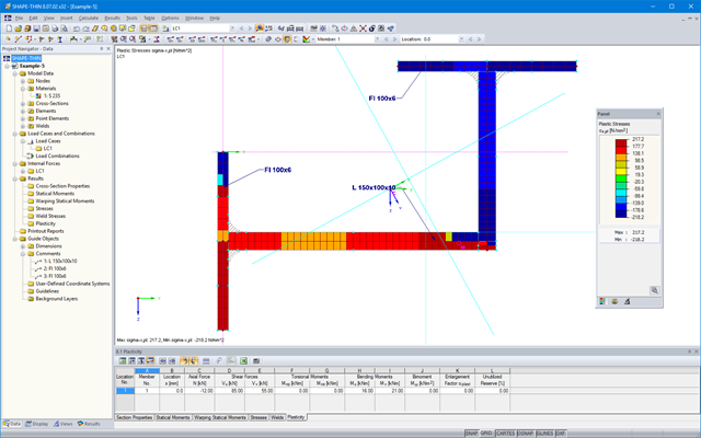
SHAPE-THIN określa wszystkie odpowiednie charakterystyki przekroju, wraz z plastycznymi siłami granicznymi i momentami. Nakładające się powierzchnie są uwzględniane w sposób realistyczny. Dla przekrojów utworzonych z różnych materiałów, SHAPE-THIN określa idealne charakterystyki przekroju w odniesieniu do materiału referencyjnego.
Oprócz analizy naprężeń w stanie sprężystym, można prowadzić również obliczenia w stanie plastycznym, zawierające interakcję sił wewnętrznych dla różnorodnych kształtów przekroju. Obliczenia interakcji plastycznej prowadzane są według metody Simplex. Podczas analizy naprężeń można wybrać różne teorie (Tresca lub von Mises).
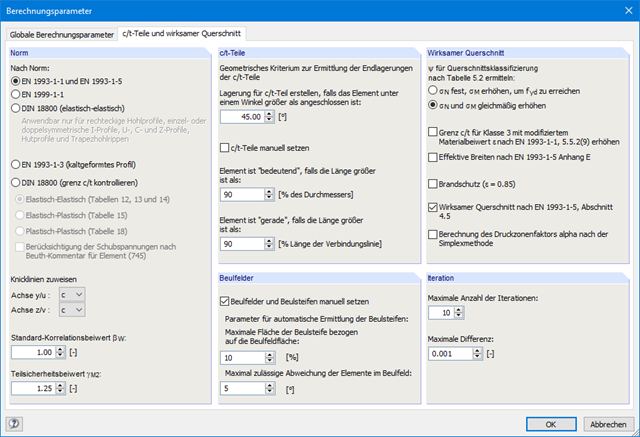
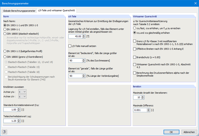
SHAPE-THIN przeprowadza klasyfikację przekroju zgodnie z EN 1993-1-1 i EN 1999-1-1. W przypadku przekrojów stalowych o przekroju 4, program określa szerokości efektywne dla płyt usztywnionych lub nieusztywnionych, zgodnie z EN 1993-1-1 i EN 1993-1-5. W przypadku przekrojów aluminiowych o przekroju klasy 4, program oblicza grubości efektywne zgodnie z EN 1999-1-1.
Opcjonalnie SHAPE-THIN sprawdza wartości graniczne c/t zgodnie z metodami obliczeniowymi el-el, el-pl lub pl-pl zgodnie z DIN 18800. Przekrój jest klasyfikowany według danej kombinacji sił wewnętrznych.

Wymiarowanie prętów stalowych formowanych na zimno zgodnie z AISI S100-16/CSA S136-16 jest dostępne w RFEM 6. Dostęp do obliczeń można uzyskać, wybierając normy „AISC 360” lub „CSA S16” w rozszerzeniu Projektowanie konstrukcji stalowych. Następnie dla obliczeń elementów formowanych na zimno automatycznie wybierane jest „AISI S100” lub „CSA S136”.
Do obliczania sprężystego obciążenia wyboczeniowego pręta program RFEM stosuje metodę DSM. Bezpośrednia metoda wytrzymałości oferuje dwa typy rozwiązań, numeryczne (metoda pasm skończonych) i analityczne (specyfikacja). Krzywą charakterystyczną (sygnaturę) FSM i kształty wyboczenia można wyświetlić w oknie dialogowym Przekroje.
- Wyniki wymiarowania połączeń można wprowadzić do protokołu wydruku
- Podczas tworzenia nowego protokołu wydruku należy wybrać elementy dodane z rozszerzenia Połączenia stalowe
- Za pomocą narzędzia 'Drukowanie grafik do protokołu' można wstawić do protokołu grafikę z wynikami połączenia, w tym z panelem sterowania.
- Protokół wydruku zawiera specyfikacje elementów połączenia, parametry obliczeniowe, wyniki i grafiki
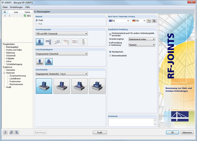
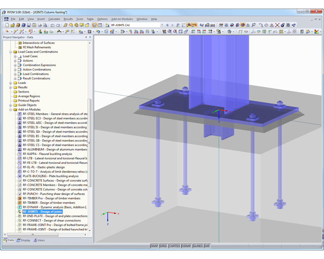
W kategorii Fundamenty przegubowe dostępne są cztery różne połączenia z blachą podstawy:
- Prosta podstawa słupa
- Zbieżna podstawa słupa
- Podstawa słupa dla prostokątnych profili zamkniętych
- Podstawa słupa dla okrągłych profili zamkniętych
W kategorii Podparcie dla słupów dostępnych jest pięć różnych układów połączeń dwuteowników:
- Podstawa słupa bez usztywnienia
- Podstawa słupa z żebrami usztywniającymi w środku pasa
- Podstawa słupa z żebrami usztywniającymi po obu stronach słupa
- Podstawa słupa z usztywnieniami ceowymi
- Fundament kielichowy
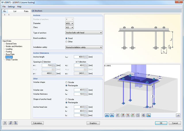
Wszystkie typy połączeń zawierają płytę podstawy przyspawaną do stalowego słupa. Połączenia za pomocą kotew są zabetonowane w fundamencie. Do wyboru są kotwy typu M12 - M42 o gatunkach stali 4.6 - 10.9. Górna i dolna strona kotew może być wyposażona w zaokrąglone lub kątowe blachy w celu lepszego rozłożenia obciążenia lub zakotwienia. Dodatkowo można zastosować prostokątne lub okrągłe głowice kotwiące z gwintem na końcach pręta.
Materiał i grubość warstwy zaprawy oraz wymiary i materiał podstawy można ustawić dowolnie. Ponadto można zdefiniować zbrojenie brzegowe stopy. Aby zapewnić lepsze przenoszenie sił tnących, na dolnej stronie blachy podstawy można zastosować skos (nakładka).
Siły tnące są przenoszone przez nakładki, kotwy lub tarcie. Poszczególne komponenty można łączyć.

W rozszerzeniu Połączenia stalowe można wymiarować połączenia zgodnie z amerykańską normą ANSI/AISC 360-16. Zintegrowane zostały następujące metody obliczeń:
- Obliczenia współczynnika obciążenia i odporności (LRFD)
- Projektowanie dopuszczalnych naprężeń (ASD)
Po wybraniu w pierwszym oknie wprowadzania typu zakotwienia i normy obliczeniowej, w oknie 1.2 należy zdefiniować węzeł, który ma zostać zaimportowany z programu RFEM/RSTAB i w którym ma zostać przeprowadzone wymiarowanie zakotwienia.
Opcjonalnie można ręcznie zdefiniować przekrój i materiał słupa. W kolejnych oknach wprowadzania można zdefiniować parametry punktu bazowego, takie jak np. Obciążenie jest importowane z programu RFEM/RSTAB lub, w przypadku ręcznej definicji połączenia, wprowadzone obciążenia.
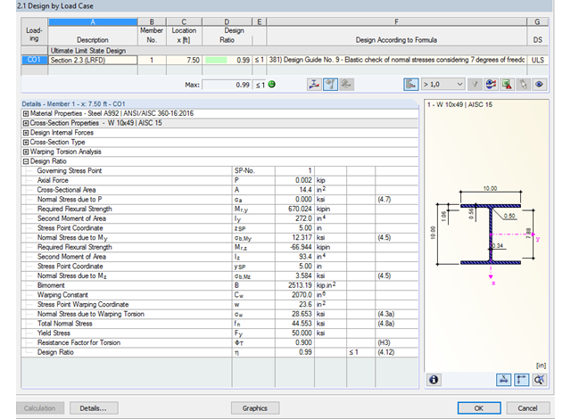
Dzięki zintegrowanemu rozszerzeniu modułu RF-/STEEL Warping Torsion, możliwe jest przeprowadzenie obliczeń zgodnie z Design Guide 9 w RF-/STEEL AISC.
Obliczenia są przeprowadzane z 7 stopniami swobody zgodnie z teorią skręcania skrępowanego i umożliwiają realistyczne obliczenia stateczności z uwzględnieniem skręcania.

W rozszerzeniu Połączenia stalowe można klasyfikować sztywności połączeń.
Oprócz sztywności początkowej w tabeli wyświetlane są również wartości graniczne dla połączeń przegubowych i sztywnych dla wybranych sił wewnętrznych N, My i/lub Mz. Uzyskana klasyfikacja jest następnie wyświetlana w tabeli jako „przegubowa”, „półsztywna” i „sztywna”.
Przejdź do filmu
W rozszerzeniu „Połączenia stalowe” można uwzględnić naprężenie wstępne śrub w obliczeniach dla wszystkich komponentów. Sprężenie można łatwo aktywować za pomocą pola wyboru w parametrach śruby i ma ono wpływ zarówno na analizę naprężeniowo-odkształceniową, jak i na analizę sztywności.
Śruby sprężone to specjalne śruby stosowane w konstrukcjach stalowych w celu wygenerowania dużej siły zaciskowej między połączonymi elementami konstrukcyjnymi. Ta siła docisku powoduje tarcie między elementami konstrukcyjnymi, co umożliwia przenoszenie sił.
Funkcjonalność
Śruby sprężane są dokręcane z określonym momentem, co powoduje ich rozciąganie i powstawanie siły rozciągającej. Ta siła rozciągająca jest przenoszona na połączone elementy i prowadzi do powstania dużej siły mocującej. Siła zaciskowa zapobiega poluzowaniu połączenia i zapewnia niezawodne przenoszenie siły.
Zalety
- Wysoka nośność: Śruby wstępnie rozciągane mogą przenosić duże siły.
- Niskie odkształcenie: Minimalizują odkształcenie połączenia.
- Wytrzymałość zmęczeniowa: Są odporne na zmęczenie.
- Łatwość montażu: Są one stosunkowo łatwe w montażu i demontażu.
Analiza i wymiarowanie
Obliczenia śrub sprężanych są przeprowadzane w RFEM z wykorzystaniem modelu analitycznego ES wygenerowanego przez rozszerzenie "Połączenia stalowe". Uwzględnia ona siłę zwarcia, tarcie między elementami konstrukcyjnymi, wytrzymałość śrub na ścinanie oraz nośność elementów konstrukcyjnych. Wymiarowanie odbywa się zgodnie z DIN EN 1993-1-8 (Eurokod 3) lub amerykańską normą ANSI/AISC 360-16. Utworzony model analityczny wraz z wynikami można zapisać i wykorzystać jako niezależny model w programie RFEM.
SHAPE-THIN posiada obszerną bibliotekę przekrojów walcowanych i parametryzowanych. Mogą one być łączone lub uzupełniane o nowe elementy. Możliwe jest zamodelowanie przekroju składającego się z różnych materiałów.
Narzędzia i funkcje graficzne umożliwiają modelowanie złożonych kształtów przekrojów w sposób typowy dla programów CAD. W oknie graficznym można wprowadzić elementy punktowe, spoiny pachwinowe, łuki, sparametryzowane przekroje prostokątne i okrągłe, elipsy, łuki eliptyczne, parabole, hiperbole, splajn oraz NURBS. Alternatywnie można zaimportować plik DXF, który stanowi podstawę do dalszego modelowania. Podczas modelowania można użyć także linii pomocniczych.
Ponadto, sparametryzowane wprowadzanie danych umożliwia wprowadzanie danych modelu i obciążeń w określony sposób, tak aby były one zależne od określonych zmiennych.
Elementy można graficznie podzielić lub przydzielić do innych obiektów. SHAPE-THIN automatycznie dzieli elementy i zapewnia nieprzerwany przepływ ścinający poprzez wprowadzenie elementów zerowych. W przypadku elementów zerowych można zdefiniować określoną grubość, aby kontrolować przenoszenie ścinania.
W przypadku elementów połączenia można sprawdzić, czy utrata stateczności jest istotna. Wymaga to rozszerzenia Stateczność konstrukcji.
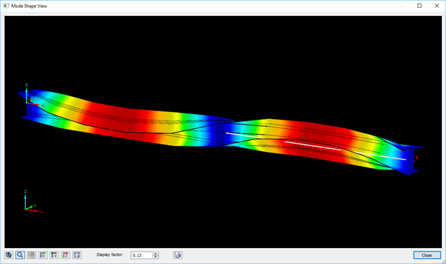
Współczynnik obciążenia krytycznego obliczany jest dla wszystkich analizowanych kombinacji obciążeń oraz wybranej liczby postaci własnych dla modelu połączenia. Porównaj najmniejszy współczynnik obciążenia krytycznego z wartością graniczną 15 z normy EN 1993-1-1, rozdz. 5. Ponadto użytkownik może samodzielnie dostosować wartość graniczną. Wynikiem analizy stateczności jest wyświetlenie w programie graficznej postaci odpowiednich postaci drgań.
Na potrzeby analizy stateczności dostosowany model powierzchniowy jest wykorzystywany w programie RFEM do rozpoznania lokalnych kształtów wyboczeniowych. Można również zapisać model analizy stateczności wraz z wynikami i wykorzystać jako osobny plik modelu.
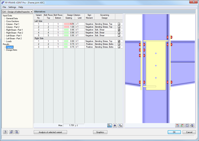
RF-/FRAME-JOINT Pro przeprowadza następujące obliczenia według EN 1993-1-8 lub DIN 18800:
- Płyta czołowa belki i półka słupa według teorii przegubu plastycznego
- Sworznie dla rozciągania (wraz z siłami kontaktowymi)
- Sworznie dla ścinania
- Wprowadzanie siły rozciągającej w środniku słupa i środniku belki
- Obliczanie wyboczenia dla płyty wachlarzowej
- Obliczanie ścinania dla płyty wachlarzowej
- Wprowadzanie siły ściskającej w środniku słupa oraz obliczanie wyboczenia dla płyty środnika
- W razie potrzeby:
- Obliczanie usztywnienia poprzecznego
- usztywnienie w środniku
- Wzmocnienie środnika dodatkową blachą
- Wprowadzanie siły ściskającej w belce poziomej
- Projektowanie spoin
Główne funkcje wymiarowania połączeń są najpierw pogrupowane i wyświetlane wraz z podstawową geometrią połączenia w pierwszym oknie wyników. W innych tabelach wyników można zobaczyć wszystkie podstawowe szczegóły obliczeń, takie jak nośność na docisk, ścinanie, poślizg i inne.
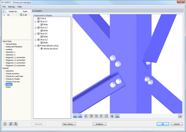
Wymiary, właściwości materiału i spoiny istotne dla konstrukcji połączenia są wyświetlane natychmiast i można je wydrukować. Połączenie może zostać przedstawione graficznie w module dodatkowym RF-/JOINTS Steel - Tower lub bezpośrednio w modelu programu RFEM/RSTAB.
Wszystkie grafiki mogą zostać dołączone do protokołu wydruku programu RFEM/RSTAB lub wydrukowane bezpośrednio. Dzięki skalowaniu wyników, możliwa jest optymalna kontrola wizualna już na etapie projektowania.
Definiowanie krytycznego momentu wyboczeniowego odbywa się w module RF-/STEEL AISC za pomocą solwera wartości własnych, który umożliwia dokładne określenie krytycznego obciążenia wyboczeniowego.
Solwer wartości własnych pokazuje okno z grafiką wartości własnych, które umożliwia sprawdzenie warunków brzegowych.
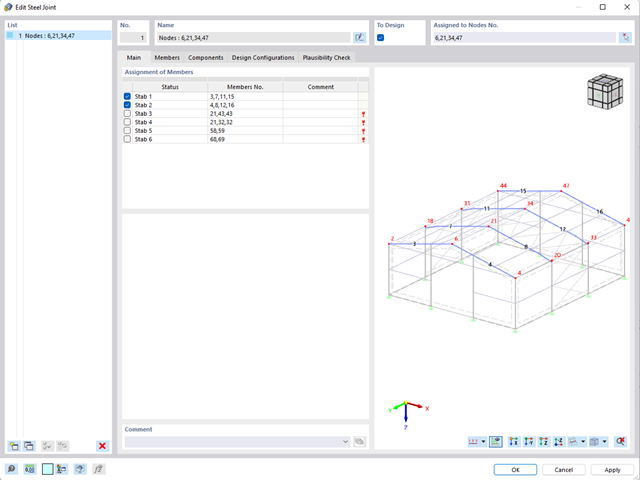
- W przypadku nowego modelu połączenia należy wybrać węzeł w modelu RFEM
- Po wybraniu węzła pręty połączone z węzłem są automatycznie rozpoznawane i przydzielane
- W oknie służącym do przydzielania prętów należy wybrać pręty, które zostaną przydzielone do połączenia
- Zaznaczone przez nas pręty są wyświetlane w oknie podglądu po prawej stronie
- Połączenia mogą być modelowane dla wielu węzłów w konstrukcji.
- Jako ustawienia prętów należy wybrać te, które mają być podparte
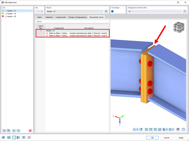
- Równolegle do wprowadzania danych program przeprowadza kontrolę poprawności, aby szybko wykryć brakujące dane wejściowe lub kolizje.
- W przypadku błędu pojawia się komunikat opisujący problem.
- Modelowanie przekroju za pomocą elementów, profili, łuków i elementów punktowych
- Biblioteka właściwości materiałów, granic plastyczności i naprężeń granicznych, którą użytkownik może rozbudowywać
- Właściwości przekrojów otwartych, zamkniętych i niepołączonych
- Efektywne właściwości przekrojów wykonanych z różnych materiałów
- Określanie naprężeń w spoinach pachwinowych
- Analiza naprężeń wraz z obliczaniem skręcania swobodnego i skrępowanego
- Sprawdzanie stosunków (c/t)
- Przekroje efektywne według
- EN 1993-1-5 (w tym płyty usztywnione zgodnie z rozdziałem 4.5)
-
 EN 1993-1-3
 -
EN 1999-1-1
-
 DIN 18800-2
- Klasyfikacja według
-
EN 1993-1-1
-
EN 1999-1-1
-
- Interfejs z MS Excel służący do importu i eksportu tabel
- Raport
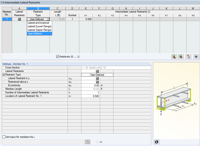
W programie STEEL AISC możliwe jest uwzględnienie pośrednich podpór bocznych w dowolnym miejscu. Na przykład, możliwa jest stabilizacja tylko górnej półki.
Ponadto można przypisać boczne podpory pośrednie zdefiniowane przez użytkownika; na przykład pojedyncze sprężyny obrotowe i sprężyny translacyjne w dowolnym miejscu przekroju.
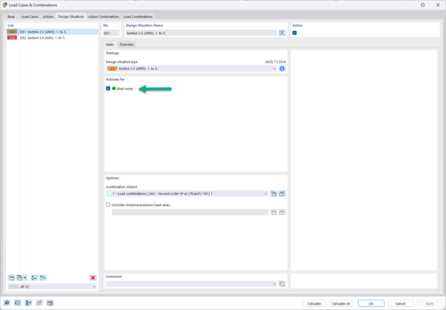
- Elementy łączące są obliczane zgodnie z AISC 360-16 i Eurokodem EN 1993-1-8.
- Po aktywacji rozszerzenia sytuacje obliczeniowe dla połączeń stalowych należy aktywować w oknie dialogowym „Przypadki obciążeń i kombinacje”.
- Do obliczenia stateczności (wyboczenia) połączenia wymagane jest rozszerzenie 'Stateczność konstrukcji'.
- Obliczenia można uruchomić za pomocą tabeli lub ikony w górnym pasku.
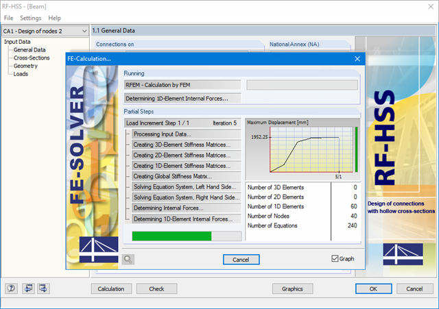
Pomyślne sprawdzenie obliczeń opiera się na sprawdzeniu poprawności warunków geometrycznych.
RF-/HSS prowadzi analizę dla następujących typów obliczeń:
- Uszkodzenie półki w belce pasa spowodowane siłą normalną
- Uszkodzenie przez ścięcie prętów pasa spowodowane siłą normalną
- Uszkodzenie zastrzału spowodowane siłą normalną
- Przebicie spowodowane siłą normalną