53 Wyniki
Wyświetl wyniki:
Sortuj według:

Rozszerzenie Projektowanie konstrukcji drewnianych dla RFEM umożliwia wymiarowanie prętów i powierzchni zgodnie z Eurokodem 5, SIA 265 (norma szwajcarska), CSA O86 (norma kanadyjska) lub ANSI/AWC NDS (norma amerykańska), np. drewno klejone krzyżowo, drewno klejone warstwowo, drewno iglaste, materiały drewnopochodne itp.
Przejdź do filmu
W przypadku powierzchni drewnianych o grubości "Stała" uwzględniany jest współczynnik zarysowania kcr, a tym samym negatywny wpływ rys na wytrzymałość na ścinanie.

- 002374
- Ogólne informacje
- Projektowanie konstrukcji drewnianych RFEM 6
- Projektowanie konstrukcji drewnianych RSTAB 9
Jak zapewne wiesz, weryfikacje są przeprowadzane dla wybranych prętów z uwzględnieniem zdefiniowanego czasu zwęglania. Wszystkie niezbędne współczynniki i współczynniki redukcyjne są zapisywane w programie i uwzględniane przy określaniu nośności konstrukcji. Pozwala to zaoszczędzić dużo pracy.
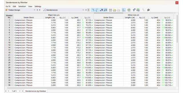
Długości efektywne dla obliczeń pręta zastępczego są pobierane bezpośrednio z danych dotyczących wytrzymałości. Nie trzeba ich ponownie wprowadzać.
Po zakończeniu obliczeń program wyświetla w przejrzysty sposób obliczenia odporności ogniowej ze wszystkimi szczegółami wyników. Pozwala to na przejrzyste śledzenie wyników. Wyniki zawierają również wszystkie wymagane parametry, dzięki czemu można określić temperaturę elementu w czasie projektowania.
Oprócz wszystkich tych funkcji, program umożliwia zintegrowanie wszystkich tabel wyników i grafik, w tym wyników stanu granicznego nośności i użytkowalności, z globalnym protokołem wydruku programu RFEM/RSTAB, jako część wyników obliczeń stali.

W programach RFEM i RSTAB można wymiarować pręty przy użyciu materiału typu "Fornir klejony warstwowo". Dostępni są następujący producenci:
- Pollmeier (Baubuche)
- Metsä (kerto LVL)
- STEICO
- Stora Enso
W konfiguracji stanu granicznego nośności można uwzględnić współczynniki wytrzymałości w celu zwiększenia wytrzymałości. Niezależnie od tego współczynniki zmniejszające wytrzymałości są uwzględniane automatycznie. Wypróbuj teraz!
Przejdź do filmu
Czy jesteś gotowy na ocenę? Skorzystaj z wykresów obliczeniowych, które pokazują rozkład określonego wyniku podczas obliczeń.
Przypisanie osi pionowej i poziomej wykresu obliczeniowego można dowolnie definiować. Umożliwia to np. wyświetlenie przebiegu osiadania określonego węzła w zależności od obciążenia.

Można ocenić przekroje wynikowe dla obliczeń powierzchni drewnianych w sposób graficzny. Z jednej strony w grafice programu RFEM, az drugiej strony w oknie historii wyników. Przekroje można umieszczać w dowolnym miejscu w celu szczegółowej oceny wyników obliczeń.

Czy chcesz modelować i analizować zachowanie bryły gruntowej? Aby to zapewnić, w programie RFEM zaimplementowano odpowiednie modele materiałowe.
Można użyć zmodyfikowanego modelu Mohra-Coulomba z liniowo-sprężystym modelem idealnie plastycznym lub nieliniowo sprężystym modelem z edometryczną relacją naprężenie-odkształcenie. Kryterium graniczne, które opisuje przejście od obszaru sprężystości do obszaru płynięcia plastycznego, jest zdefiniowane według Mohra-Coulomba.
- 002134
- Ogólne informacje
- Projektowanie konstrukcji drewnianych RFEM 6
- Projektowanie konstrukcji drewnianych RSTAB 9
- Wymiarowanie elementów rozciąganych, ściskanych, zginanych, ścinanych, skręcanych i poddanych połączonemu działaniu tych sił wewnętrznych
- Uwzględnienie podcięcia
- Obliczanie ściskania prostopadle do włókien na podporach końcowych i pośrednich z (EC 5) i bez elementów wzmacniających (śruby z pełnym gwintem)
- Opcjonalna redukcja siły tnącej na podporze
- Wymiarowanie prętów zakrzywionych i zbieżnych
- Uwzględnianie wyższych wytrzymałości dla podobnych elementów, które znajdują się blisko siebie (współczynnik ksys wg EN 1995-1-1, 6.6(1)-(3))
- Możliwość zwiększenia nośności na ścinanie dla drewna iglastego zgodnie z DIN EN 1995‑1‑1:NA NDP do 6.1.7(2)
- 002135
- Obliczenia
- Projektowanie konstrukcji drewnianych RFEM 6
- Projektowanie konstrukcji drewnianych RSTAB 9
- Analiza stateczności dla wyboczenia giętnego, wyboczenia skrętnego i wyboczenia giętno-skrętnego przy ściskaniu
- Import długości efektywnych z obliczeń przy użyciu rozszerzenia Stateczność konstrukcji
- Graficzne wprowadzanie i kontrola zdefiniowanych podpór węzłowych oraz długości efektywnych w celu analizy stateczności
- Określanie długości zastępczych prętów o zbieżnym przekroju
- Uwzględnienie położenia stężenia zwichrzenia
- Analiza zwichrzenia elementów poddanych obciążeniu momentem
- W zależności od normy istnieje wybór między wprowadzaniem wartości Mcr przez użytkownika, metodą analityczną z normy lub wykorzystaniem wewnętrznego solwera wartości własnych
- Uwzględnienie panelu usztywniającego i ograniczenia obrotu podczas korzystania z solwera wartości własnych
- Graficzne przedstawienie postaci własnej w przypadku zastosowania solwera wartości własnych
- Analiza stateczności elementów konstrukcyjnych ze ściskaniem i naprężeniem zginającym, w zależności od normy obliczeniowej
- Przejrzyste obliczenia wszystkich niezbędnych współczynników, takich jak współczynniki uwzględniające rozkładu momentów lub współczynniki interakcji
- Alternatywne uwzględnienie wszystkich wpływów dla analizy stateczności podczas określania sił wewnętrznych w programie RFEM/RSTAB (analiza drugiego rzędu, imperfekcje, redukcja sztywności, ewentualnie w połączeniu z rozszerzeniem Skręcanie skrępowane (7 stopni swobody))

- 002377
- Ogólne informacje
- Projektowanie konstrukcji drewnianych RFEM 6
- Projektowanie konstrukcji drewnianych RSTAB 9
Masz wiele możliwości w projektowaniu konstrukcji drewnianych. Dla prętów o zmiennym przekroju i zakrzywionych, możliwe jest uwzględnienie kątów nacięcia względem włókien, naprężeń rozciągających poprzecznych oraz zależnych od objętości promieni krzywizny. Aby obliczyć pole przekroju włókien, wytrzymałość na rozciąganie lub zginanie jest odpowiednio dostosowywana. Aby umożliwić również przeprowadzenie analizy stateczności metodą prętów zastępczych, wysokość do wyznaczenia długości efektywnej i długości wyboczeniowej została ustawiona jako odległość 0,65 × h od rzeczywistego punktu obliczeniowego.
.png?mw=640&hash=403c565ab80c4dd45c2d1356634fb74a90428b70)
W bibliotece konstrukcji warstwowych dostępni są następujący producenci drewna klejonego krzyżowo:
- Binderholz (USA)
- KLH (USA, CAN)
- Kalesnikoff (USA, CAN)
- Nordic Structures (USA, CAN)
- Mercer Mass Timber
- SmartLam
- Sterling Structural
- Konstrukcje nośne wymienione w Lignatec wydanie 32 "Drewno klejone krzyżowo z produkcji szwajcarskiej"
Wczytanie konstrukcji z biblioteki konstrukcji warstw powoduje automatyczne przejęcie wszystkich istotnych parametrów. Biblioteka jest stale aktualizowana.

W porównaniu z modułem dodatkowym RF-SOILIN (RFEM 5) do rozszerzenia Analiza geotechniczna dla programu RFEM 6 dodano następujące nowe funkcje:
- Tworzenie warstwowego gruntu jako modelu 3D z całości zdefiniowanych próbek gruntu
- Symulacja gruntu zgodnie z teorią Mohra-Coulomba
- Graficzne i tabelaryczne przedstawienie naprężeń i odkształceń na dowolnej głębokości gruntu
- Optymalne uwzględnienie interakcji gruntu i konstrukcji na podstawie modelu ogólnego

W programie RFEM zaimplementowano bibliotekę płyt z drewna klejonego krzyżowo, z której można importować konstrukcje warstwowe różnych producentów (np. Binderholz, KLH, Piveteaubois, Södra, Züblin Timber, Schilliger, Stora Enso). Oprócz grubości i materiałów warstw podane są również informacje o redukcji sztywności i łączeniu wąskich boków.
Przejdź do filmu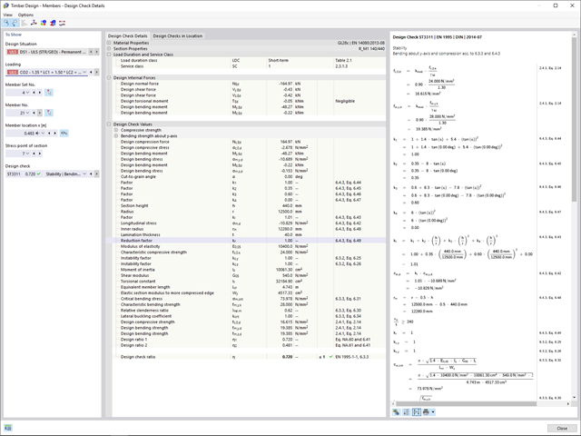
- 002172
- Ogólne informacje
- Projektowanie konstrukcji drewnianych RFEM 6
- Projektowanie konstrukcji drewnianych RSTAB 9
W porównaniu z modułem dodatkowym RF-/TIMBER Pro (RFEM 5/RSTAB 8) do rozszerzenia Projektowanie konstrukcji drewnianych dla programu RFEM 6/RSTAB 9 dodano następujące nowe funkcje:
- Oprócz Eurokodu 5, uwzględnione zostały inne międzynarodowe normy (SIA 265, ANSI/AWC NDS, CSA O86, GB 50005)
- Obliczanie ściskania prostopadle do włókien (ciśnienie na podporze)
- Wprowadzenie solwera wartości własnych do wyznaczania momentu krytycznego dla wyboczenia skrętnego (tylko EC 5)
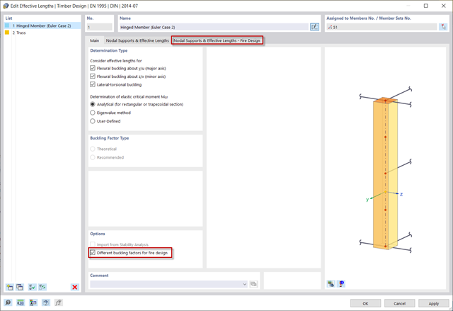
- Definicja różnych długości efektywnych do obliczeń w normalnej temperaturze i odporności ogniowej
- Ocena naprężeń poprzez naprężenia jednostkowe (MES)
- Zoptymalizowane analizy stateczności dla prętów o zbieżnym przekroju
- Ujednolicenie materiałów dla wszystkich załączników krajowych (w bibliotece materiałów dostępna jest teraz tylko jedna norma „EN”)
- Wyświetlanie osłabień przekrojów bezpośrednio w renderingu
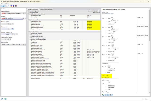
- Wyświetlanie odpowiednich wzorów użytych do sprawdzania warunków nośności (w tym odniesienie do zastosowanego równania z normy)

Bryły gruntu, które mają zostać przeanalizowane, są sumowane w masywach gruntu.
Próbki gruntu należy wykorzystać jako podstawę do zdefiniowania masywu gruntowego. W ten sposób program umożliwia generowanie masywu w sposób przyjazny dla użytkownika, w tym automatyczne określanie granic faz na podstawie danych z próbki, a także poziomu wód gruntowych i podpór powierzchni granicznej.
Masywy gruntowe umożliwiają określenie docelowego rozmiaru siatki ES niezależnie od ustawień globalnych dla reszty konstrukcji. Dzięki temu w całym modelu można uwzględnić różne wymagania dotyczące budynku i gruntu.

Twoje dane są zawsze dokumentowane w wielojęzycznym raporcie. W każdej chwili możesz dostosować treść i zapisać ją jako szablon. W raporcie można również za pomocą kilku kliknięć umieścić grafiki, teksty, wzory MathML i dokumenty PDF.
- 002378
- Ogólne informacje
- Projektowanie konstrukcji drewnianych RFEM 6
- Projektowanie konstrukcji drewnianych RSTAB 9
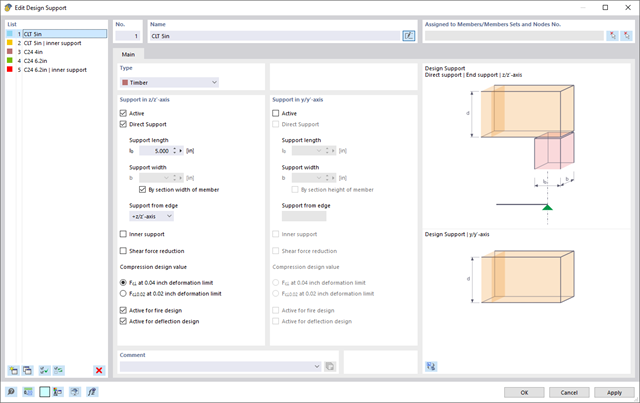
Tutaj masz wolny wybór. Obliczenie ciśnienia w podporach można przeprowadzić w dowolnym punkcie dla obciążenia w kierunkach y i z przekroju. Użytkownik może dowolnie rozróżnić podpory wewnętrzne i zewnętrzne. Użytkownik może zdefiniować współczynnik kc,90 dla parcia prostopadłego do włókien (np. 1,75 dla drewna klejonego warstwowo). Jeżeli jest to dozwolone, długość podpory jest automatycznie zwiększana zgodnie ze specyfikacjami normy. Dzięki temu można przeprowadzić bardziej efektywne obliczenia przy minimalnym wysiłku.
Wiesz już, że grunt i konstrukcję można modelować i analizować w całym modelu. Oznacza to, że wyraźnie uwzględniono interakcję gleba-konstrukcja. Dostosowanie jednego elementu konstrukcyjnego prowadzi do natychmiastowego prawidłowego uwzględnienia w analizie i wynikach dla całego układu gruntu i konstrukcji.
- 002373
- Ogólne informacje
- Projektowanie konstrukcji drewnianych RFEM 6
- Projektowanie konstrukcji drewnianych RSTAB 9
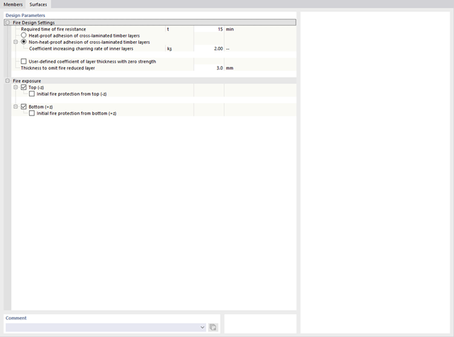
Program RFEM/RSTAB oferuje również szereg funkcji na wypadek pożaru. Program umożliwia automatyczne generowanie kombinacji obciążeń i wyników dla wyjątkowej sytuacji obliczeniowej w obliczeniach odporności ogniowej. Pręty, które mają zostać zwymiarowane wraz z odpowiednimi siłami wewnętrznymi, są importowane bezpośrednio z programu RFEM/RSTAB. Przechowywane są również wszystkie informacje o materiale i przekroju. Nie musisz'robić nic więcej.
Parametry istotne dla obliczeń odporności ogniowej można definiować poprzez przypisanie konfiguracji odporności ogniowej do obliczanych prętów i powierzchni. Ponadto można wprowadzić dalsze szczegółowe ustawienia, takie jak zdefiniowanie ekspozycji na ogień z jednej strony aż po wszystkie strony.
.png?mw=640&hash=55038d2a1591f62179796666cb9b2fede0274e19)
Graficzne i tabelaryczne wyświetlanie wyników dla deformacji, naprężeń i odkształceń pomaga określić bryłę gruntu. Aby to osiągnąć, skorzystaj ze specjalnych kryteriów filtrowania, które umożliwiają wybór określonych wyników.
Program na pewno cię nie zawiedzie. Jeśli chcesz graficznie ocenić wyniki w bryłach gruntu, dostępne są obiekty pomocnicze. Na przykład można zdefiniować płaszczyzny przycinania. Umożliwia to przeglądanie odpowiednich wyników na dowolnej płaszczyźnie bryły gruntu.
I nie tylko to. Wykorzystanie przekrojów wyników i brył przycinania ułatwia graficzną analizę brył gruntu.

Czy wiecie, że...? Uwarstwienie gruntu, pobrane z raportów o podłożu gruntowym w miejscach wychodni, można wprowadzić bezpośrednio do programu w postaci próbek gruntu. Przypisz badane materiały gruntowe wraz z ich właściwościami do warstw.
Za pomocą danych tabelarycznych i okna dialogowego edycji można zdefiniować próbkę. Można również określić poziom wód gruntowych w próbkach gruntu.

Czy wiecie, że...? W podporach obliczeniowych można teraz zdefiniować śruby z pełnym gwintem jako poprzeczne elementy wzmacniające ściskanie dla obliczenia "Ściskania w poprzek włókien". Śruby są sprawdzane pod kątem wciśnięcia i wyboczenia.
Dodatkowo sprawdzana jest nośność na ścinanie w płaszczyźnie wierzchołka śruby. Kąt rozłożenia obciążenia można uwzględnić liniowo poniżej 45° lub nieliniowo (zgodnie z Bejtka, I. (2005). Verstärkung von Bauteilen aus holz mit vollgewindeschrauben. KIT Scientific Publishing.
- 002384
- Ogólne informacje
- Projektowanie konstrukcji drewnianych RFEM 6
- Projektowanie konstrukcji drewnianych RSTAB 9
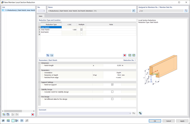
Redukcja przekroju pręta umożliwia uwzględnienie podcięcia początkowego, wewnętrznego lub końcowego belki. Redukcja belki jest zatem uwzględniana w obliczeniach nośności. Nie dotyczy to jednak sztywności.
- 002385
- Ogólne informacje
- Projektowanie konstrukcji drewnianych RFEM 6
- Projektowanie konstrukcji drewnianych RSTAB 9
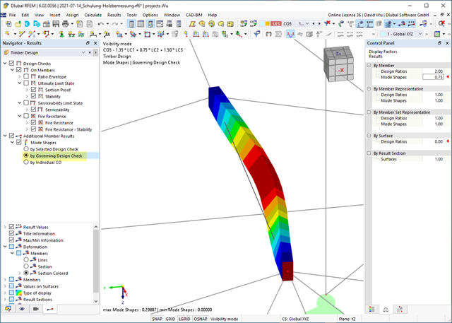
Czy do określenia współczynnika obciążenia krytycznego w ramach analizy stateczności użyto solwera wartości własnych rozszerzenia? W takim przypadku można wyświetlić decydujący kształt drgań własnych projektowanego obiektu. W tym miejscu dostępny jest solwer wartości własnych do analizy zwichrzenia, w zależności od zastosowanej normy obliczeniowej.
- 002496
- Ogólne informacje
- Projektowanie konstrukcji drewnianych RFEM 6
- Projektowanie konstrukcji drewnianych RSTAB 9
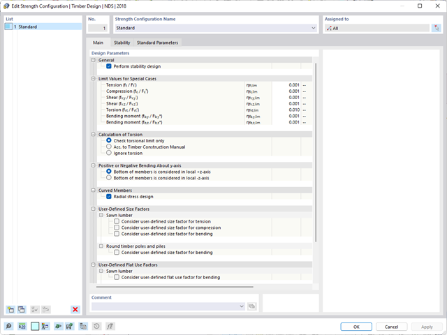
Występuje skręcanie? W takim przypadku to Ty decydujesz o sposobie przeprowadzenia obliczeń. Do dyspozycji masz następujące opcje:
- Zezwól na dalsze obliczenia, jeżeli naprężenie styczne od skręcania nie przekracza wartości granicznej
- Wymiarowanie zgodnie z Timber Construction Manual, 4.6
- Ignorowanie skręcania
Wprowadzanie warstw gruntu dla potrzeb zadawania próbek gruntu odbywa się w przejrzystym oknie dialogowym. Odpowiadająca temu prezentacja graficzna zapewnia przejrzystość i ułatwia kontrolę wprowadzanych danych.
Rozszerzalna baza danych ułatwia wybór właściwości materiałowych dla gruntu. Dla realistycznego odwzorowania zachowania się materiału gruntowego można użyć modelu Mohra-Coulomba oraz model gruntu ze wzmocnieniem.
Można zdefiniować dowolną liczbę próbek i warstw gruntu. Grunt jest odwzorowany na podstawie wszystkich wprowadzonych próbek za pomocą brył 3D. Przypisanie do konstrukcji odbywa się za pomocą współrzędnych.
Zachowanie bryły gruntu jest obliczane za pomocą nieliniowej metody iteracyjnej. Obliczone naprężenia i osiadania są wyświetlane graficznie oraz w tabelach.
- 002381
- Ogólne informacje
- Projektowanie konstrukcji drewnianych RFEM 6
- Projektowanie konstrukcji drewnianych RSTAB 9
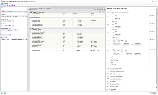
Dzięki oprogramowaniu Dlubal wszystko jest łatwiejsze. Przeprowadzone obliczenia normy projektowej są przedstawione w przejrzysty sposób. Dla każdego warunku projektowego określane jest kryterium obliczeniowe. Ponadto program dostarcza szczegółowe informacje na temat obliczeń, w tym wartości początkowe, wyniki pośrednie i wyniki końcowe. Proces obliczeń wraz z zastosowanymi wzorami, standardowymi źródłami i wynikami szczegółowo przedstawiony jest w oknie informacyjnym w szczegółach obliczeń.
- 002380
- Ogólne informacje
- Projektowanie konstrukcji drewnianych RFEM 6
- Projektowanie konstrukcji drewnianych RSTAB 9
Co się dzieje, gdy jest z wiatrem? Stężenie giętno-skrętne nie jest stosowane w celu zredukowania długości efektywnych i długości zwichrzenia.

Wyniki naprężeń i odkształceń według powierzchni można wyświetlić w tabeli wyników powierzchni zgodnie z grubością warstwy.
- 002379
- Ogólne informacje
- Projektowanie konstrukcji drewnianych RFEM 6
- Projektowanie konstrukcji drewnianych RSTAB 9
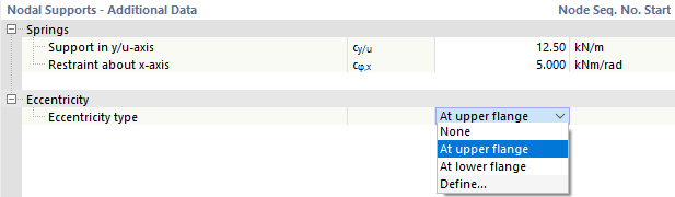
Dla podpór bocznych konstrukcji często nie są przeprowadzane obliczenia odporności ogniowej. Chcesz rozwiązać ten problem w swoim projekcie? Aby uwzględnić ten fakt w obliczeniach, można zdefiniować inne długości prętów zastępczych dla sytuacji pożarowej.