139 Wyniki
Wyświetl wyniki:
Sortuj według:

W rozszerzeniu Połączenia stalowe można łączyć profile zamknięte o przekroju okrągłym za pomocą spoin.
Profile okrągłe można łączyć ze sobą lub z płaskimi elementami konstrukcyjnymi. Spoiną można również łączyć pachwiny przekrojów znormalizowanych i cienkościennych.
Przejdź do filmu
W rozszerzeniu Projektowanie konstrukcji stalowych można przeprowadzić kontrolę obliczeń stateczności i przekrojów profili formowanych na zimno według EN 1993-1-3, zgodnie z punktami 6.1.2 - 6.1.5 i 6.1.8 - 6.1.10.
Przejdź do filmu
W rozszerzeniu Połączenia stalowe można klasyfikować sztywności połączeń.
Oprócz sztywności początkowej w tabeli wyświetlane są również wartości graniczne dla połączeń przegubowych i sztywnych dla wybranych sił wewnętrznych N, My i/lub Mz. Uzyskana klasyfikacja jest następnie wyświetlana w tabeli jako „przegubowa”, „półsztywna” i „sztywna”.
Przejdź do filmu
W rozszerzeniu „Połączenia stalowe” można uwzględnić naprężenie wstępne śrub w obliczeniach dla wszystkich komponentów. Sprężenie można łatwo aktywować za pomocą pola wyboru w parametrach śruby i ma ono wpływ zarówno na analizę naprężeniowo-odkształceniową, jak i na analizę sztywności.
Śruby sprężone to specjalne śruby stosowane w konstrukcjach stalowych w celu wygenerowania dużej siły zaciskowej między połączonymi elementami konstrukcyjnymi. Ta siła docisku powoduje tarcie między elementami konstrukcyjnymi, co umożliwia przenoszenie sił.
Funkcjonalność
Śruby sprężane są dokręcane z określonym momentem, co powoduje ich rozciąganie i powstawanie siły rozciągającej. Ta siła rozciągająca jest przenoszona na połączone elementy i prowadzi do powstania dużej siły mocującej. Siła zaciskowa zapobiega poluzowaniu połączenia i zapewnia niezawodne przenoszenie siły.
Zalety
- Wysoka nośność: Śruby wstępnie rozciągane mogą przenosić duże siły.
- Niskie odkształcenie: Minimalizują odkształcenie połączenia.
- Wytrzymałość zmęczeniowa: Są odporne na zmęczenie.
- Łatwość montażu: Są one stosunkowo łatwe w montażu i demontażu.
Analiza i wymiarowanie
Obliczenia śrub sprężanych są przeprowadzane w RFEM z wykorzystaniem modelu analitycznego ES wygenerowanego przez rozszerzenie "Połączenia stalowe". Uwzględnia ona siłę zwarcia, tarcie między elementami konstrukcyjnymi, wytrzymałość śrub na ścinanie oraz nośność elementów konstrukcyjnych. Wymiarowanie odbywa się zgodnie z DIN EN 1993-1-8 (Eurokod 3) lub amerykańską normą ANSI/AISC 360-16. Utworzony model analityczny wraz z wynikami można zapisać i wykorzystać jako niezależny model w programie RFEM.

Sztywność początkowa Sj,ini jest parametrem decydującym o ocenie, czy połączenie można scharakteryzować jako sztywne, niesztywne czy przegubowe.
W rozszerzeniu „Połączenia stalowe” można obliczyć początkowe sztywności Sj,ini zgodnie z Eurokodem (EN 1993-1-8 sekcja 5.2.2) i AISC (AISC 360-16 Cl. E3.4) w odniesieniu do sił wewnętrznych N, My i/lub Mz.
Opcjonalne automatyczne przenoszenie sztywności początkowych umożliwia bezpośrednie przenoszenie sztywności przegubowych na końcach prętów w programie RFEM. Następnie cała konstrukcja jest ponownie obliczana, a wynikające z niej siły wewnętrzne są automatycznie uwzględniane jako obciążenia w obliczeniach i wymiarowaniu modeli połączeń.
Ten zautomatyzowany proces iteracji eliminuje konieczność ręcznego eksportu i importu danych, zmniejszając ilość pracy i minimalizując potencjalne źródła błędów.
Film wyjaśniający: Obliczanie sztywności początkowej Sj,ini
Wymiarowanie prętów stalowych formowanych na zimno zgodnie z AISI S100-16/CSA S136-16 jest dostępne w RFEM 6. Dostęp do obliczeń można uzyskać, wybierając normy „AISC 360” lub „CSA S16” w rozszerzeniu Projektowanie konstrukcji stalowych. Następnie dla obliczeń elementów formowanych na zimno automatycznie wybierane jest „AISI S100” lub „CSA S136”.
Do obliczania sprężystego obciążenia wyboczeniowego pręta program RFEM stosuje metodę DSM. Bezpośrednia metoda wytrzymałości oferuje dwa typy rozwiązań, numeryczne (metoda pasm skończonych) i analityczne (specyfikacja). Krzywą charakterystyczną (sygnaturę) FSM i kształty wyboczenia można wyświetlić w oknie dialogowym Przekroje.

Rozszerzenie Połączenia stalowe umożliwia wymiarowanie połączeń prętów o złożonych przekrojach. Ponadto można przeprowadzać obliczenia połączeń dla prawie wszystkich przekrojów cienkościennych z biblioteki programu RFEM.
Przejdź do filmu
W tym przypadku projektowanie spoin staje się dziecinnie proste. Dzięki specjalnie opracowanemu modelowi materiałowemu „Ortotropowy | Plastyczny | Spoina (Powierzchnie)" można obliczyć wszystkie składowe naprężenia w sposób plastyczny. Naprężenie Tprostopadłe jest również rozpatrywane w sposób plastyczny.
Korzystanie z tego modelu materiałowego umożliwia realistyczne i ekonomiczne projektowanie spoin.
Film wyjaśniający
Za pomocą komponentu "Blacha łącząca" można automatycznie utworzyć nową blachę węzłową w rozszerzeniu Połączenia stalowe. Pozwala to na zaoszczędzenie oddzielnych komponentów, a pozostałe elementy, takie jak blacha czołowa i blacha nakładkowa, są automatycznie uwzględniane wraz z wymiarami.
Przejdź do filmu
Aby określić nośność śrub na ścinanie, w rozszerzeniu Połączenia stalowe można określić, czy w połączeniu na ścinanie znajduje się trzpień czy gwint.
Przejdź do filmu
W przypadku spoiny łączącej dwie płyty z różnych materiałów, można teraz wybrać z pola rozwijanego, który z obu materiałów ma zostać użyty do utworzenia spoiny.
Przejdź do filmu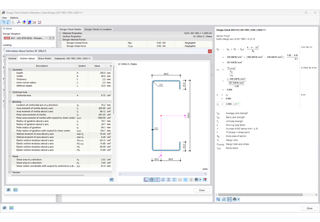
Chcesz przeprowadzić kontrolę przekrojów prętów stalowych zimnogiętych zgodnie z EN 1993-1-3? Niezależnie od tego, czy są to profile zimnogięte z biblioteki przekrojów, czy też przekroje ogólne formowane na zimno (nieperforowane) z RSECTION, program do analizy statyczno-wytrzymałościowej pomoże w definiowaniu przekroju efektywnego z uwzględnieniem wyboczenia lokalnego i niestateczności. Można również przeprowadzić kontrolę przekroju zgodnie z EN 19 93 1 3, sekcja 6 1 6. W takim przypadku siły wewnętrzne z obliczeń z wykorzystaniem Skręcania skrępowanego (7 stopni swobody) są uwzględniane za pomocą kontroli naprężeń zastępczych
Przejdź do filmu
Złożone połączenie belek poziomych ze słupem oraz połączenie stężeń ukośnych
Model połączenia został zamodelowany przy użyciu około 50 komponentów. Model został stworzony na podstawie rzeczywistego przykładu wykorzystania w konstrukcji.

Stalowe połączenia śrubowe z blachami węzłowymi na konstrukcji zadaszenia.
Pobierz model do analizy statyczno-wytrzymałościowej i otwórz go w programie RFEM 6, korzystając z rozszerzenia Połączenia stalowe.

W przypadku przekrojów prostokątnych zwykle można uzyskać bezpośrednie połączenie za pomocą spoin. W ten sam sposób można je jednak połączyć z innymi przekrojami. Ponadto inne elementy, takie jak blachy czołowe, pomagają w łączeniu przekrojów prostokątnych z innymi elementami konstrukcyjnymi.

Podczas wymiarowania zgodnie z EN 1993-1-3, możliwe jest przedstawienie graficzne postaci własnej wyboczenia dystorsyjnego przekroju oraz dla przekrojów RSECTION.
Kształt postaci własnej można również wyprowadzić w RSECTION 1 dla przekrojów z biblioteki.

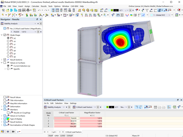
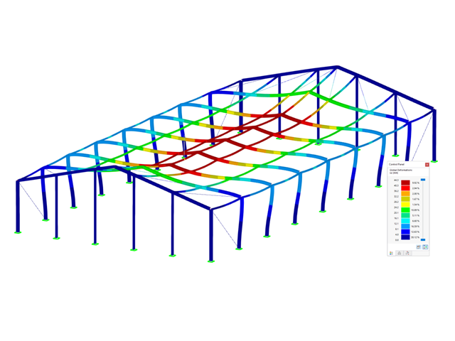
Wymiarowanie połączenia ramy o prętach zbieżnych i usztywnionych. Dla połączenia przeprowadzono analizę naprężeń i stateczności przy wyboczeniu. Aby wyświetlić wyniki dla wyboczenia, połączenie zostało przekształcone w osobny model.

- Proponowane połączenie można zastosować do wszystkich wybranych węzłów w konstrukcji
- Położenie połączenia można zdefiniować w zakładce 'Główne' okna dialogowego rozszerzenia
- Obliczenia są przeprowadzane dla wszystkich połączeń w konstrukcji, a po zakończeniu obliczeń wyniki mogą być wyświetlane we wszystkich połączeniach
- W tabeli wyświetlane są wyniki dla poszczególnych połączeń, każde połączenie jest obliczane i może być zapisane osobno
- Elementy łączące są obliczane zgodnie z AISC 360-16 i Eurokodem EN 1993-1-8.
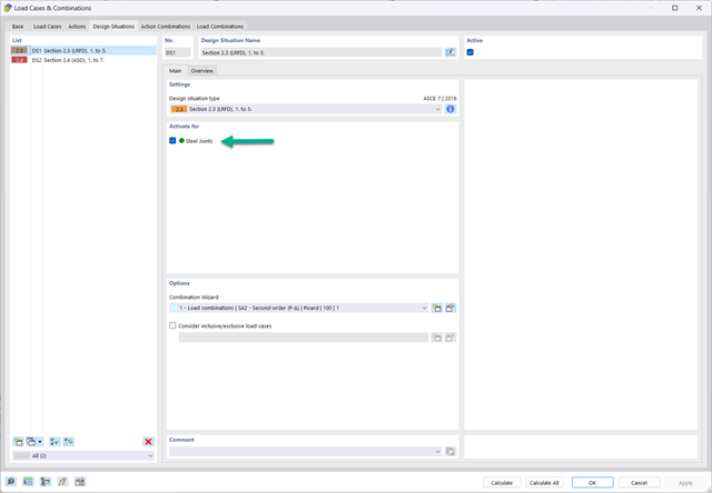
- Po aktywacji rozszerzenia sytuacje obliczeniowe dla połączeń stalowych należy aktywować w oknie dialogowym „Przypadki obciążeń i kombinacje”.
- Do obliczenia stateczności (wyboczenia) połączenia wymagane jest rozszerzenie 'Stateczność konstrukcji'.
- Obliczenia można uruchomić za pomocą tabeli lub ikony w górnym pasku.
- Model połączeń stalowych i wyniki można zapisać jako osobny plik modelu
- Uzyskane naprężenia i wyniki analizy stateczności (wyboczenia połączenia) można wyświetlić w osobnym modelu
- W zapisanym modelu można uruchomić animację deformacji połączenia
- Elementy połączenia są podczas zapisywania przekształcane w powierzchnie i pręty
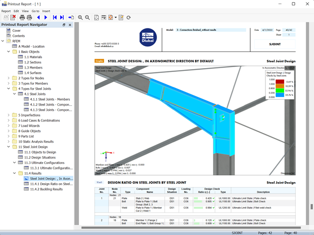
- Wyniki wymiarowania połączeń można wprowadzić do protokołu wydruku
- Podczas tworzenia nowego protokołu wydruku należy wybrać elementy dodane z rozszerzenia Połączenia stalowe
- Za pomocą narzędzia 'Drukowanie grafik do protokołu' można wstawić do protokołu grafikę z wynikami połączenia, w tym z panelem sterowania.
- Protokół wydruku zawiera specyfikacje elementów połączenia, parametry obliczeniowe, wyniki i grafiki

- 002133
- Ogólne informacje
- Projektowanie konstrukcji drewnianych RFEM 6
- Projektowanie konstrukcji drewnianych RSTAB 9
- Szeroki wybór przekrojów, takich jak przekroje prostokątne, kwadratowe, teowe, okrągłe, złożone, nieregularne przekroje parametryczne i wiele innych (przydatność do obliczeń zależy od wybranej normy)
- Wymiarowanie drewna klejonego krzyżowo (CLT)
- Wymiarowanie materiałów drewnopochodnych i drewna klejonego warstwowo zgodnie z EC 5
- Wymiarowanie prętów o zmiennym przekroju (metoda zgodna z normą)
- Możliwe jest dostosowanie istotnych współczynników obliczeniowych i parametrów normowych
- Elastyczność dzięki szczegółowym opcjom ustawień dla podstawy i zakresu obliczeń
- Szybkie i przejrzyste wyświetlanie wyników dla globalnej oceny ich rozkładu na konstrukcji po zakończeniu obliczeń
- Szczegółowe wyniki obliczeń i niezbędne wzory (jasna i łatwa do zweryfikowania ścieżka wyników)
- Przejrzyste zestawienie wyników w formie numerycznej w stosownych oknach oraz możliwość ich graficznego przedstawienia na konstrukcji
- Integracja wyników z protokołem wydruku programu RFEM/RSTAB

- 002372
- Ogólne informacje
- Projektowanie konstrukcji drewnianych RFEM 6
- Projektowanie konstrukcji drewnianych RSTAB 9
- Dowolna definicja czasu zwęglania
- W przypadku konstrukcji powierzchniowych (drewno klejone krzyżowo) można obliczyć z przyczepnością lub bez
- Bezpłatna, zdefiniowana przez użytkownika specyfikacja parametrów pożaru
- Uwzględnienie różnych długości efektywnych do obliczania odporności ogniowej
- Opcjonalne obliczenia dla 'ściskania w poprzek włókien'
- Zintegrowane z RFEM/RSTAB graficzne wyświetlanie wyników, np. B. Stopień wykorzystania
- Pełna integracja wyników z protokołem wydruku programu RFEM/RSTAB
- 002385
- Ogólne informacje
- Projektowanie konstrukcji drewnianych RFEM 6
- Projektowanie konstrukcji drewnianych RSTAB 9
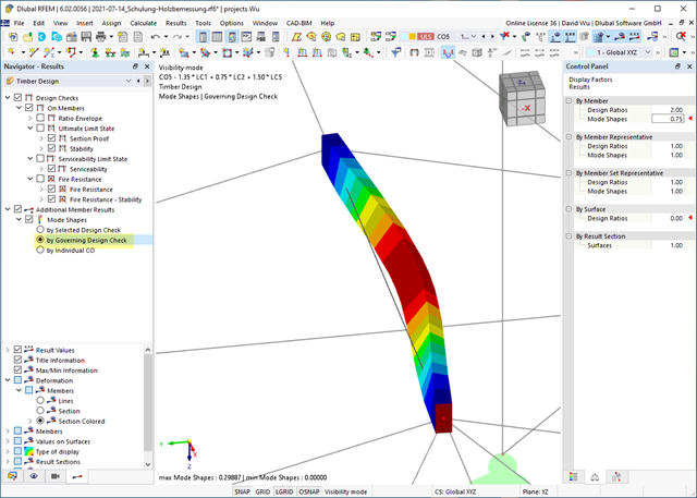
Czy do określenia współczynnika obciążenia krytycznego w ramach analizy stateczności użyto solwera wartości własnych rozszerzenia? W takim przypadku można wyświetlić decydujący kształt drgań własnych projektowanego obiektu. W tym miejscu dostępny jest solwer wartości własnych do analizy zwichrzenia, w zależności od zastosowanej normy obliczeniowej.
- 002387
- Obliczenia
- Projektowanie konstrukcji drewnianych RFEM 6
- Projektowanie konstrukcji drewnianych RSTAB 9
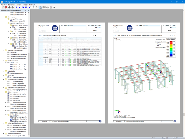
Jeśli projekt się powiedzie, nadejdzie czas. Ponieważ program wykonuje za Ciebie wiele procesów. Przeprowadzone kontrole obliczeń są na przykład wyświetlane w tabeli. Tutaj wyświetlane są wszystkie szczegóły wyników. Dzięki przejrzyście przedstawionym wzorom obliczeniowym wyniki są bezproblemowe i zrozumiałe. Nie ma tu efektu "czarnej skrzynki".
Obliczenia są przeprowadzane we wszystkich decydujących miejscach prętów i przedstawiane graficznie w postaci wykresu wyników. Ponadto w wynikach dostępne są szczegółowe grafiki, takie jak rozkład naprężeń w przekroju lub decydujący kształt postaci drgań.
Wszystkie dane wejściowe i wyniki są częścią protokołu wydruku programu RFEM/RSTAB. Zawartość protokołu i jego zakres można wybrać specjalnie dla poszczególnych warunków projektowych.
- 002317
- Ogólne informacje
- Projektowanie konstrukcji stalowych RFEM 6
- Projektowanie konstrukcji stalowych RSTAB 9
- Obliczanie ugięć i porównanie z normatywnymi lub ręcznie dostosowanymi wartościami granicznymi
- Uwzględnienie wygięcia wstępnego w analizie ugięcia
- W zależności od typu sytuacji obliczeniowej możliwe są różne wartości graniczne
- Ręczne dostosowywanie długości odniesienia i segmentacji według kierunku
- Obliczanie ugięć w odniesieniu do konstrukcji początkowej lub do konstrukcji odkształconej
- Dalsze szczegółowe obliczenia w zależności od wybranej normy obliczeniowej (np. ograniczenie oddychania środnika zgodnie z EN 1993-2)
- Graficzne wyświetlanie wyników zintegrowane z RFEM/RSTAB; na przykład stopień wykorzystania wartości granicznej, odkształcenie lub ugięcie
- Pełna integracja wyników z protokołem wydruku programu RFEM/RSTAB

- 002318
- Ogólne informacje
- Projektowanie konstrukcji stalowych RFEM 6
- Projektowanie konstrukcji stalowych RSTAB 9
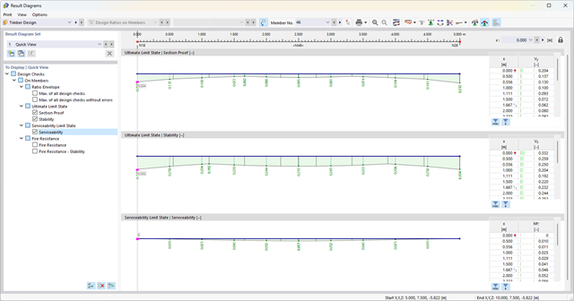
W programie RFEM/RSTAB istnieje możliwość wygenerowania, a następnie obliczenia kombinacji obciążeń lub wyników wymaganych dla stanu granicznego użytkowalności. Sytuacje obliczeniowe można wybrać do analizy ugięć w rozszerzeniu Projektowanie konstrukcji stalowych. Obliczone wartości odkształceń są odpowiednio określane w każdym miejscu pręta, w zależności od określonego wygięcia wstępnego i układu odniesienia. Na koniec można porównać te wartości odkształceń z wartościami granicznymi.
Czy wiecie, że...? Wartość graniczną deformacji można określić indywidualnie dla każdego elementu konstrukcyjnego w Konfiguracja stanu granicznego użytkowalności. Jako dopuszczalną wartość graniczną należy zdefiniować maksymalne odkształcenie w zależności od długości odniesienia. Poprzez zdefiniowanie podpór obliczeniowych można podzielić komponenty na segmenty w celu automatycznego określenia odpowiedniej długości odniesienia dla każdego kierunku obliczeń.
W zależności od położenia przydzielonych podpór obliczeniowych, rozróżnienie między belkami i wspornikami jest dokonywane automatycznie, dzięki czemu można odpowiednio określić wartość graniczną.
- 002319
- Ogólne informacje
- Projektowanie konstrukcji stalowych RFEM 6
- Projektowanie konstrukcji stalowych RSTAB 9
Zasady sprawdzania stanu granicznego użytkowalności można znaleźć w tabelach wyników w rozszerzeniu Projektowanie konstrukcji stalowych. Wyniki obliczeń można wyświetlić ze wszystkimi szczegółami w każdym miejscu obliczanych prętów. Ponadto dostępne są grafiki z wykresami wyników i stopni wykorzystania. Zapewnia to dobry przegląd sytuacji.
Wszystkie tabele wyników i grafiki można również zintegrować z globalnym protokołem wydruku programu RFEM/RSTAB jako część wyników wymiarowania stali. Dzięki temu można wyświetlać i dokumentować odkształcenia całej konstrukcji w ramach funkcji programu RFEM/RSTAB, niezależnie od rozszerzenia.
- 002320
- Ogólne informacje
- Projektowanie konstrukcji stalowych RFEM 6
- Projektowanie konstrukcji stalowych RSTAB 9
- Ręczne określenie temperatury krytycznej elementu lub automatyczne określenie temperatury elementu przez żądany czas
- Szeroki wybór krzywych pożaru: standardowa krzywa temperatura-czas, krzywa pożaru zewnętrznego, krzywa węglowodorów
- Ręczne dostosowywanie istotnych współczynników do określania temperatury stali
- Uwzględnienie cynkowania ogniowego elementów konstrukcyjnych przy określaniu temperatury stali
- Wyniki wykresu temperatura-czas dla temperatury gazu i stali
- Podczas określania temperatury można uwzględnić okładzinę ogniochronną w postaci obrysu lub okładziny skrzynkowej wykonanej z materiałów niezależnych od temperatury
- Wymiarowanie prętów ze stali węglowej lub nierdzewnej
- Obliczenia przekrojów i analiza stateczności (metoda prętów zastępczych) zgodnie z EN 1993-1-2, rozdz. 4.2.3
- Obliczenia przekrojów klasy 4 zgodnie z EN 1993-1-2, Załącznik E.
- 002321
- Ogólne informacje
- Projektowanie konstrukcji stalowych RFEM 6
- Projektowanie konstrukcji stalowych RSTAB 9
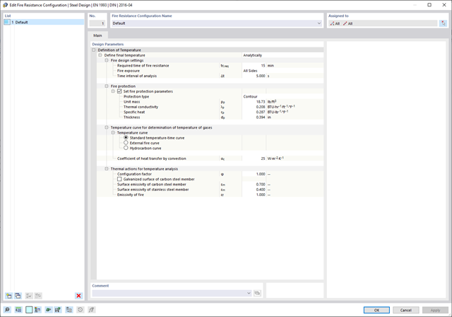
Programy do analizy statyczno-wytrzymałościowej RFEM/RSTAB oferują szereg zautomatyzowanych funkcji, które ułatwiają codzienną pracę. Jednym z nich jest automatyczne generowanie kombinacji obciążeń i wyników dla wyjątkowej sytuacji obliczeniowej w obliczeniach odporności ogniowej. Pręty, które mają zostać zwymiarowane wraz z odpowiednimi siłami wewnętrznymi, są importowane bezpośrednio z programu RFEM/RSTAB. Nie musisz'robić nic więcej. Program zachował również wszystkie informacje o materiale i przekroju.
Poprzez przypisanie konfiguracji odporności ogniowej do obliczanych prętów, użytkownik definiuje parametry istotne dla obliczeń odporności ogniowej. Tutaj można ręcznie określić krytyczną temperaturę stali w czasie projektowania. Temperaturę wyznaczaną przez program można określić automatycznie dla określonego czasu trwania pożaru. Do wyboru dostępne są różne krzywe temperatury pożaru i środki ochrony przeciwpożarowej. Można również wprowadzić dalsze szczegółowe ustawienia, takie jak zdefiniowanie ekspozycji na ogień ze wszystkich stron lub z trzech stron