26 Wyniki
Wyświetl wyniki:
Sortuj według:

Wymiarowanie prętów stalowych formowanych na zimno zgodnie z AISI S100-16/CSA S136-16 jest dostępne w RFEM 6. Dostęp do obliczeń można uzyskać, wybierając normy „AISC 360” lub „CSA S16” w rozszerzeniu Projektowanie konstrukcji stalowych. Następnie dla obliczeń elementów formowanych na zimno automatycznie wybierane jest „AISI S100” lub „CSA S136”.
Do obliczania sprężystego obciążenia wyboczeniowego pręta program RFEM stosuje metodę DSM. Bezpośrednia metoda wytrzymałości oferuje dwa typy rozwiązań, numeryczne (metoda pasm skończonych) i analityczne (specyfikacja). Krzywą charakterystyczną (sygnaturę) FSM i kształty wyboczenia można wyświetlić w oknie dialogowym Przekroje.

- 002469
- Ogólne informacje
- Projektowanie konstrukcji betonowych RFEM 6
- Projektowanie konstrukcji betonowych RSTAB 9
Pracujesz z elementami konstrukcyjnymi składającymi się z płyt? W takim przypadku należy przeprowadzić obliczenia na ścinanie z uwzględnieniem wymagań obliczania przebicia, na przykład zgodnie z 6.4, EN 1992-1-1. Oprócz płyt stropowych można w ten sposób wymiarować również płyty fundamentowe.
W konfiguracji stanu granicznego nośności dla wymiarowania betonu można zdefiniować parametry obliczeń przebicia dla wybranych węzłów.

- 002133
- Ogólne informacje
- Projektowanie konstrukcji drewnianych RFEM 6
- Projektowanie konstrukcji drewnianych RSTAB 9
- Szeroki wybór przekrojów, takich jak przekroje prostokątne, kwadratowe, teowe, okrągłe, złożone, nieregularne przekroje parametryczne i wiele innych (przydatność do obliczeń zależy od wybranej normy)
- Wymiarowanie drewna klejonego krzyżowo (CLT)
- Wymiarowanie materiałów drewnopochodnych i drewna klejonego warstwowo zgodnie z EC 5
- Wymiarowanie prętów o zmiennym przekroju (metoda zgodna z normą)
- Możliwe jest dostosowanie istotnych współczynników obliczeniowych i parametrów normowych
- Elastyczność dzięki szczegółowym opcjom ustawień dla podstawy i zakresu obliczeń
- Szybkie i przejrzyste wyświetlanie wyników dla globalnej oceny ich rozkładu na konstrukcji po zakończeniu obliczeń
- Szczegółowe wyniki obliczeń i niezbędne wzory (jasna i łatwa do zweryfikowania ścieżka wyników)
- Przejrzyste zestawienie wyników w formie numerycznej w stosownych oknach oraz możliwość ich graficznego przedstawienia na konstrukcji
- Integracja wyników z protokołem wydruku programu RFEM/RSTAB

- 002372
- Ogólne informacje
- Projektowanie konstrukcji drewnianych RFEM 6
- Projektowanie konstrukcji drewnianych RSTAB 9
- Dowolna definicja czasu zwęglania
- W przypadku konstrukcji powierzchniowych (drewno klejone krzyżowo) można obliczyć z przyczepnością lub bez
- Bezpłatna, zdefiniowana przez użytkownika specyfikacja parametrów pożaru
- Uwzględnienie różnych długości efektywnych do obliczania odporności ogniowej
- Opcjonalne obliczenia dla 'ściskania w poprzek włókien'
- Zintegrowane z RFEM/RSTAB graficzne wyświetlanie wyników, np. B. Stopień wykorzystania
- Pełna integracja wyników z protokołem wydruku programu RFEM/RSTAB
- 002385
- Ogólne informacje
- Projektowanie konstrukcji drewnianych RFEM 6
- Projektowanie konstrukcji drewnianych RSTAB 9
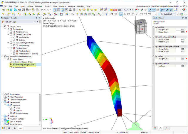
Czy do określenia współczynnika obciążenia krytycznego w ramach analizy stateczności użyto solwera wartości własnych rozszerzenia? W takim przypadku można wyświetlić decydujący kształt drgań własnych projektowanego obiektu. W tym miejscu dostępny jest solwer wartości własnych do analizy zwichrzenia, w zależności od zastosowanej normy obliczeniowej.
- 002387
- Obliczenia
- Projektowanie konstrukcji drewnianych RFEM 6
- Projektowanie konstrukcji drewnianych RSTAB 9
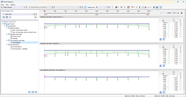
Jeśli projekt się powiedzie, nadejdzie czas. Ponieważ program wykonuje za Ciebie wiele procesów. Przeprowadzone kontrole obliczeń są na przykład wyświetlane w tabeli. Tutaj wyświetlane są wszystkie szczegóły wyników. Dzięki przejrzyście przedstawionym wzorom obliczeniowym wyniki są bezproblemowe i zrozumiałe. Nie ma tu efektu "czarnej skrzynki".
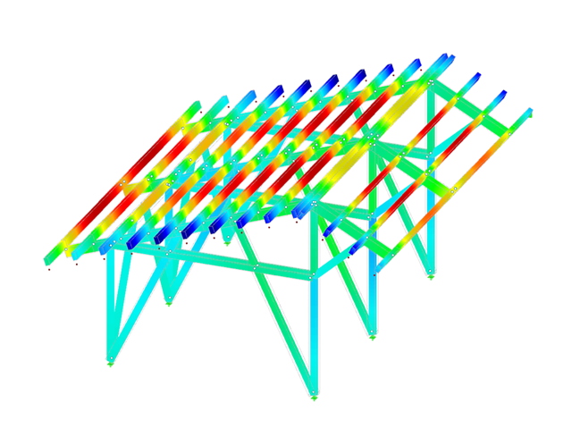
Obliczenia są przeprowadzane we wszystkich decydujących miejscach prętów i przedstawiane graficznie w postaci wykresu wyników. Ponadto w wynikach dostępne są szczegółowe grafiki, takie jak rozkład naprężeń w przekroju lub decydujący kształt postaci drgań.
Wszystkie dane wejściowe i wyniki są częścią protokołu wydruku programu RFEM/RSTAB. Zawartość protokołu i jego zakres można wybrać specjalnie dla poszczególnych warunków projektowych.
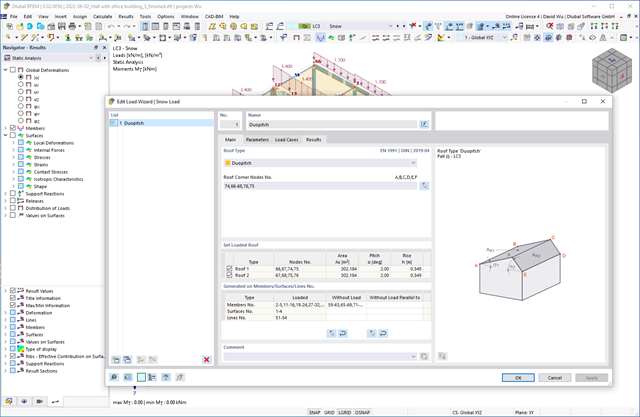
Czy chcesz, aby Twoje konstrukcje pozostały pionowe nawet podczas wiatru i śniegu? W takim razie skorzystaj z generatorów obciążeń dla konstrukcji płytowych i ramowych. Teraz można generować obciążenia wiatrem zgodnie z EN 1991‑1-4 oraz obciążenia śniegiem zgodnie z EN 1991‑1‑3 (a także innymi normami międzynarodowymi). Przypadki obciążeń są generowane w zależności od kształtu dachu.
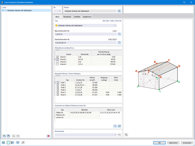
Obciążenia wiatrem również nie stanowią problemu w obliczeniach. Obciążenia wiatrem mogą być generowane automatycznie jako obciążenia prętowe lub obciążenia powierzchniowe (RFEM) na następujących elementach konstrukcyjnych:
- Ściany pionowe
- Dachy płaskie
- Dachy jednospadowe
- Dachy dwuspadowe/korytowe
- Ściany pionowe z dachem dwuspadowym
- Ściany pionowe z dachem płaskim/jednospadowym
Dostępne są następujące normy:
-
 EN 1991-1-4 (wraz z załącznikami krajowymi)
 -
 ASCE 7
 -
 NBC
NBC -
 CTE DB-SE-AE
 -
 GB 50009
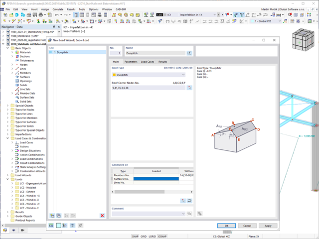
Czy Twoje konstrukcje również muszą wytrzymać opady śniegu? Za pomocą Kreatora obciążeń śniegiem można generować obciążenia śniegiem jako obciążenia prętowe lub powierzchniowe.
Dostępne są poniższe normy:
-
EN 1991-1-3 (wraz z załącznikami krajowymi)
-
ASCE 7
-
NBC
-
 SIA 261
 -
CTE DB-SE-AE
-
GB 50009
-
 IS 875
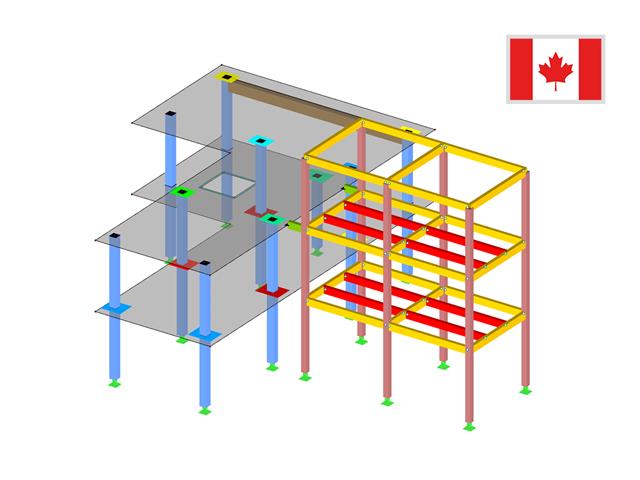
Biblioteka materiałów zawiera już kanadyjskie typy betonu i stali zbrojeniowej dostępne do przeprowadzenia wymiarowania. Jednak zawsze można zdefiniować materiały dla wymiarowania wg CSA A23.3.
Jednostki wykorzystane dla wymiarowania betonu zbrojonego wg CSA A23.3 dostosowane są dla systemu metrycznego domyślnie.
Obliczenia nośności przekroju obejmują analizę rozciągania i ściskania wzdłuż włókien, zginania, zginania i rozciągania/ściskania oraz wytrzymałości na ścinanie.
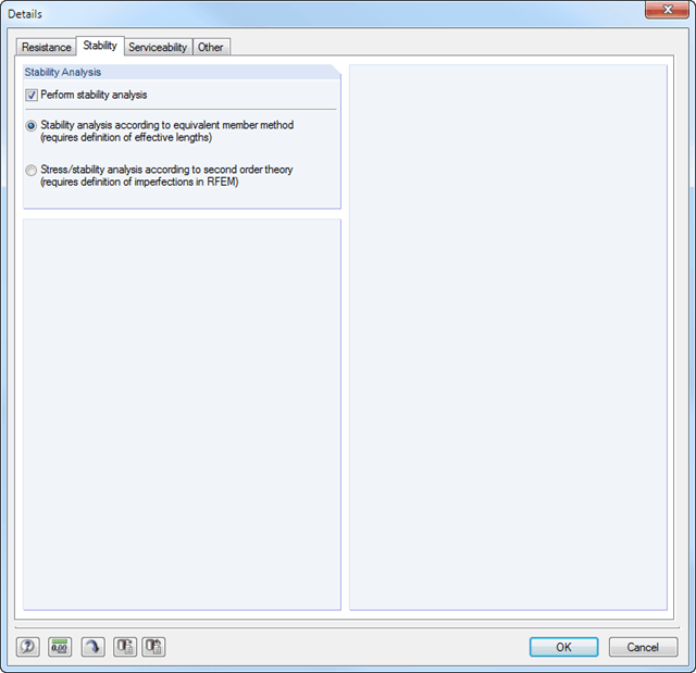
Elementy konstrukcyjne z możliwością wyboczenia i zwichrzenia są analizowane według metody pręta zastępczego i uwzględniane są systematyczne ściskanie osiowe, zginanie z lub bez siły ściskającej oraz zginanie i rozciąganie. Ugięcie wewnętrznych przęseł i wsporników jest porównywane z maksymalnym dopuszczalnym ugięciem.
Oddzielne przypadki obliczeniowe umożliwiają elastyczną analizę stateczności prętów, zbiorów prętów i obciążeń.
Parametry istotne dla obliczeń, takie jak analiza stateczności, czas trwania obciążenia w warunkach pożaru, smukłość prętów i ugięcie graniczne, można dostosowywać zgodnie z potrzebami.
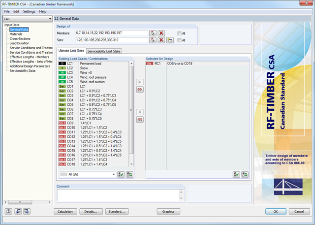
Po otwarciu modułu należy wybrać pręty/zbiory prętów, przypadki obciążeń, kombinacje obciążeń lub kombinacje wyników dla obliczeń stanu granicznego nośności i użytkowalności. Materiały z programu RFEM/RSTAB są wstępnie ustawione i można je dostosować w RF-/TIMBER CSA. Charakterystyki materiałowe zgodne z odpowiednimi normami zapisane są w bibliotece.
Podczas sprawdzania przekrojów można określić, czy uwzględniany jest przekrój wybrany w programie RFEM/RSTAB, czy przekrój zmodyfikowany. Następnie można zdefiniować klasy trwania obciążenia, warunki wilgotnościowe oraz obróbkę drewna.
Do analizy deformacji wymagane są długości referencyjne odpowiednich prętów i zbiorów prętów. Ponadto można zdefiniować określony kierunek ugięcia, wygięcie wstępne i typ belki.
W przypadku obliczeń odporności ogniowej można zdefiniować strony zwęglenia pręta lub zbioru prętów.
- Wymiarowanie prętów na rozciąganie, ściskanie, zginanie, ścinanie i kombinację sił wewnętrznych
- Analiza stateczności dla wyboczenia i zwichrzenia według metody pręta zastępczego lub analizy drugiego rzędu
- Analiza stateczności dla wyboczenia i zwichrzenia według metody pręta zastępczego lub teorii drugiego rzędu
- Dowolna konfiguracja czasu i prędkości zwęglania oraz dowolny wybór stron zwęglania do obliczeń odporności ogniowej
- Swobodne ustalenie szybkości zwęglania, czasu oraz stron narażonych na działanie ognia przy obliczaniu odporności ogniowej
- Kanadyjska baza materiałów i biblioteka przekrojów
- Zdefiniowane przez użytkownika wprowadzanie przekrojów prostokątnych i okrągłych
- Automatyczna optymalizacja przekrojów
- Możliwość importowania długości wyboczeniowych z modułu dodatkowego RF-STABILITY/RSBUCK
- Szczegółowa dokumentacja wyników wraz z odniesieniami do równań obliczeniowych z zastosowanej normy
- Różne opcje filtrowania i sortowania wyników
- Uwzględnienie wpływu warunków wilgotności drewna
- Wizualizacja kryterium obliczeniowego na modelu w programie RFEM/RSTAB
- Eksport danych do MS Excel
- Jednostki metryczne i imperialne
Podczas modelowania konstrukcji szkieletowych dostępne są generatory obciążenia wiatrem według EN 1991-1-4 oraz śniegiem według EN 1991-1-3. Przypadki obciążeń są generowane w zależności od kształtu dachu. Inny generator tworzy obciążenie pokrywą (lód). Powtarzające się kombinacje obciążeń można zapisywać jako szablony.
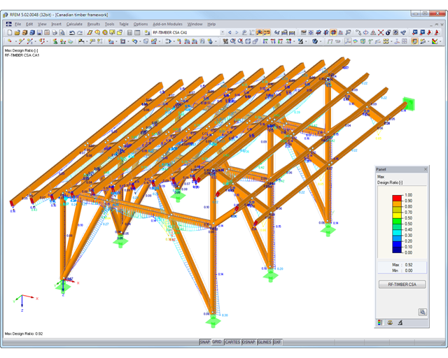
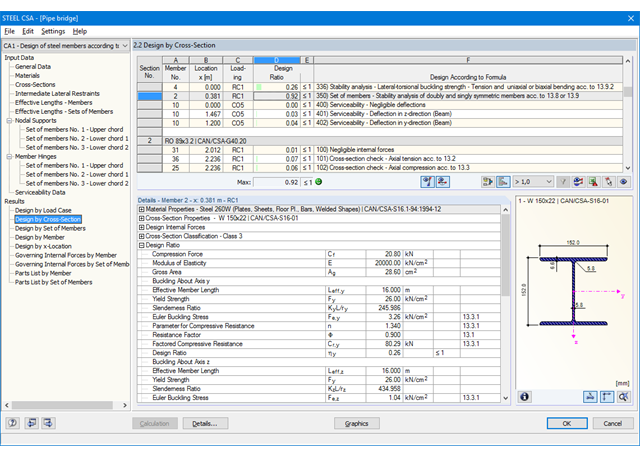
Po zakończeniu obliczeń wyniki wyświetlane są w przejrzyście ułożonych tabelach. Aby obliczenia były bardziej przejrzyste, można uwzględnić wszystkie wartości pośrednie (np. decydujące siły wewnętrzne, współczynniki korekcyjne itp.). Wyniki są posortowane według przypadków obciążenia, przekrojów, zbiorów prętów i prętów. Jeżeli analiza nie powiedzie się, przekroje, których to dotyczy, można zmodyfikować w procesie optymalizacji.
Stopień wykorzystania jest przedstawiony na modelu w programie RFEM/RSTAB za pomocą kolorów. W ten sposób można szybko rozpoznać obszary krytyczne lub przewymiarowane. Dokładną ocenę zapewniają wykresy wyników wyświetlane na pręcie lub zbiorze prętów.
Oprócz danych wejściowych i wyników, w tym szczegółowych informacji dotyczących obliczeń, wyświetlanych w tabelach, do protokołu wydruku można dodać wszystkie grafiki. W ten sposób dokumentacja jest przejrzysta i zrozumiała. Użytkownik może dostosować zawartość protokołu i żądany zakres wyników dla poszczególnych warunków projektowych.
Dane dotyczące materiału, obciążeń i kombinacji obciążeń muszą zostać wprowadzone w programie RFEM/RSTAB zgodnie z założeniami obliczeniowymi opisanymi w CSA S16. Biblioteka programu RFEM/RSTAB zawiera już odpowiednie materiały dla tej normy.
RFEM/RSTAB automatycznie tworzy odpowiednie kombinacje obciążeń zgodne z kanadyjską normą. Wszystkie kombinacje można jednak utworzyć również ręcznie w programie RFEM/RSTAB. W module RF-/STEEL CSA wybiera się najpierw pręty i zbiory prętów, które mają zostać obliczone, a także przypadki obciążeń, kombinacje obciążeń i kombinacje wyników.
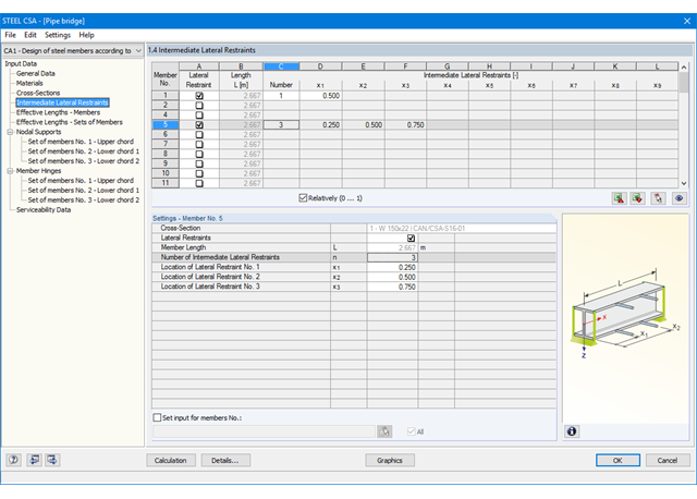
W dalszych krokach można dostosować wstępnie zdefiniowane ustawienia dla bocznych podpór pośrednich i długości efektywnych. W przypadku prętów ciągłych można zdefiniować indywidualne warunki podparcia i mimośrody każdego węzła pośredniego pojedynczych prętów. Specjalne narzędzie MES określa następnie obciążenia krytyczne i momenty wymagane do analizy stateczności w takich sytuacjach.

- Wymiarowanie prętów i zbiorów prętów dla rozciągania, ściskania, zginania, ścinania, kombinacji sił wewnętrznych i skręcania
- Analiza stateczności przy wyboczeniu, wyboczeniu skrętnym i giętno-skrętnym
- Automatyczne określanie krytycznych obciążeń wyboczeniowych i krytycznych momentów wyboczeniowych dla ogólnych obciążeń i warunków podparcia za pomocą specjalnego programu MES (analizy wartości własnych) zintegrowanego w module
- Alternatywne obliczenia analityczne krytycznego momentu wyboczeniowego dla sytuacji standardowych
- Możliwość zastosowania oddzielnych podpór bocznych do belek i prętów ciągłych
- Automatyczna klasyfikacja przekroju
- Obliczenia w stanie granicznym użytkowalności (ugięcie)
- Optymalizacja przekroju
- Szeroki wybór dostępnych przekrojów, takich jak dwuteowniki walcowane; ceowniki; teowniki; kątowniki; profile zamknięte prostokątne i okrągłe; pręty okrągłe; przekroje symetryczne i niesymetryczne, parametryczne przekroje dwuteowe, teowe, kątowniki; podwójne kątowniki
- Przejrzyście rozmieszczone okna wprowadzania i wyników
- Szczegółowa dokumentacja wyników wraz z odniesieniami do równań obliczeniowych z zastosowanej normy
- Różne opcje filtrowania i sortowania wyników, w tym wyświetlanie wyników według prętów, przekrojów, położenia x lub przypadków obciążenia, kombinacji obciążeń i kombinacji wyników
- Tabele wyników dla smukłości prętów i głównych sił wewnętrznych
- Wykaz części z parametrami masy i masy
- Pełna integracja z programem RFEM/RSTAB
- Jednostki metryczne i imperialne
Wygenerowane obciążenia można łatwo przenieść do programu RFEM/RSTAB w celu nakładania na inne przypadki obciążeń. Wszystkie dane z modułu mogą być włączone do protokołu wydruku programu RFEM/RSTAB.
Zawartość protokołu wydruku i zakres danych wyjściowych dla każdej analizy mogą być dobrane indywidualnie.
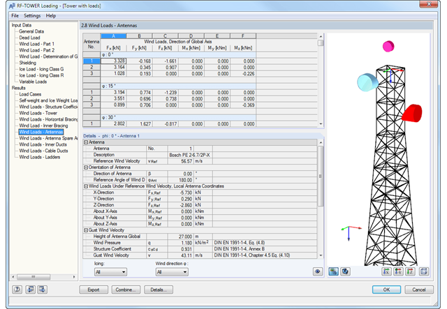
Po wygenerowaniu obciążeń można sprawdzić wyniki w przejrzyście ułożonych tabelach. Wyniki zawierają wszystkie informacje o wygenerowanych przypadkach obciążeń i obciążeń ciężarem własnym, wiatrem i lodem. Wszystkie obciążenia są wyszczególnione w obiektach konstrukcyjnych i wyposażeniu.
Moduł dodatkowy RF-/TOWER Loading spełnia wymagania norm EN 1991-1-4/DIN EN 1993-3-1, DIN 1055-4, DIN 4131: 1991-11 oraz DIN V 4131: 2008-09. Normy te obejmują specyfikacje obciążeń stałych, wiatrowych, konserwacyjnych i obciążeń lodem (ISO 12494 lub DIN 1055-5) oraz obciążeń zmiennych. Standardowe specyfikacje są ustawione fabrycznie lub dostępne w bibliotekach.
Do generowania obciążeń wiatrem zgodnie z Eurokodem dostępne są załączniki krajowe (NA) następujących krajów:
-
 DIN EN 1991-1-4 (Niemcy)
 -
 CSN EN 1994-1-4 (Republika Czeska)
 -
 NA do CYS EN 1991-1-4 (Cypr)
 -
 DK EN 1991-1-4 (Dania)
 -
 NBN EN 1991-1-4 (Belgia)
 -
 NEN EN 1991-1-4 (Holandia)
 -
 NF EN 1991-1-4 (Francja)
 -
 SFS-EN 1991-1-4 (Finlandia)
 -
 SIST EN 1991-1-4 (Słowenia)
 -
 SR EN 1991-1-4 (Rumunia)
 -
 SS EN 1991-1-4 (Singapur)
 -
 SS-EN 1991-1-4 (Szwecja)
 -
 STN EN 1991-1-4 (Słowacja)
 -
 UNI EN 1991-1-4 (Włochy)
Możliwe jest generowanie indywidualnych sytuacji obciążeniowych: Ciśnienie wiatru, kierunek wiatru lub obciążenia lodem można ustawić ręcznie lub zaimportować z tabel.
Dlubal_KohlA.png?mw=640&hash=8712eab8f6f7bd193aba63a130c51e23e354de95)
- Uwzględnienie ciężaru własnego wieży wraz z wyposażeniem
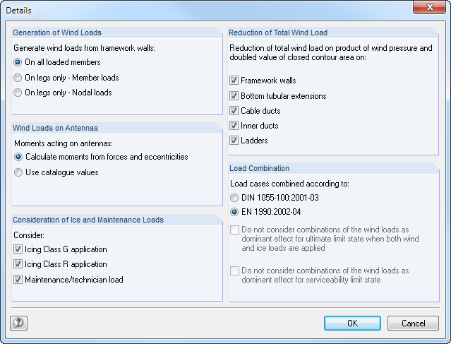
- Podział oddziaływań obciążeń wiatrowych na stronę zawietrzną i nawietrzną kratowej konstrukcji wsporczej lub definiowanie podziału według użytkownika
- Określanie obciążeń wiatrowych dla kratowej konstrukcji wsporczej i wyposażenia w przypadku konstrukcji narażonych na drgania (współczynnik podmuchu)
- Przydzielanie obciążeń powierzchniowych i skupionych do podestów
- Możliwość redukcji całkowitego obciążenia wiatrem dla wybranych obiektów
- Określanie obciążeń lodem dla klas oblodzenia G i R ze wstępnie ustawioną grubością lodu i grubością jednokierunkowego przyrostu lodu
- Generowanie przypadków obciążeń ruchomych i wywoływanych przez obsługę
Pierwsze okno wyników pokazuje maksymalne stopnie wykorzystania wraz z odpowiednim wykorzystaniem dla każdego obliczanego przypadku obciążenia (kombinacji obciążeń/kombinacji wyników).
Kolejne tabele pokazują wszystkie szczegółowe wyniki posegregowane według określonych kryteriów w rozwijanych elementach menu. Oprócz tego można wyświetlać wszystkie wyniki pośrednie dla każdego miejsca wzdłuż długości pręta. W ten sposób można łatwo prześledzić, jak w module zostały przeprowadzone poszczególne obliczenia.
Pełne dane modułu stanowią część protokołu wydruku programu RFEM/RSTAB. Użytkownik może dostosować zawartość protokołu i żądany zakres wyników dla poszczególnych warunków projektowych.
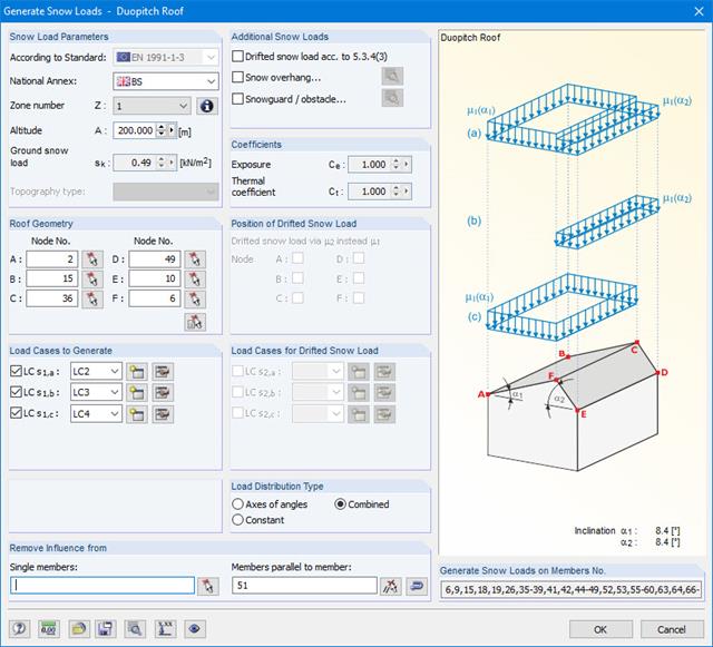
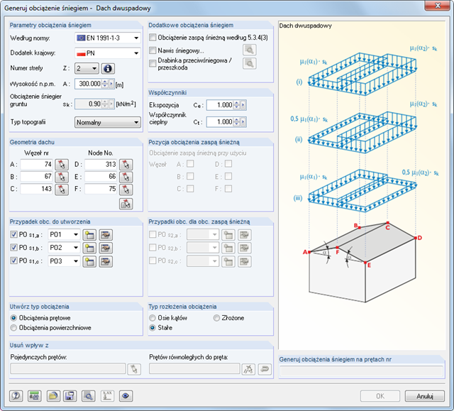
Obciążenia śniegiem mogą być generowane jako obciążenia prętów na dachach płaskich / jednospadowych i dachach dwuspadowych.
Dodatkowe obciążenia śniegiem takie jak obciążenia śniegiem naniesionym, nasypem śnieżnym i barierkami przeciwśniegowymi mogą zostać również uwzględnione.
Dostępne są poniższe normy:
-
EN 1991-1-3 (wraz z załącznikami krajowymi)
-
DIN 1055-5
-
CTE DB-SE-AE
-
ASCE/SEI 7-16
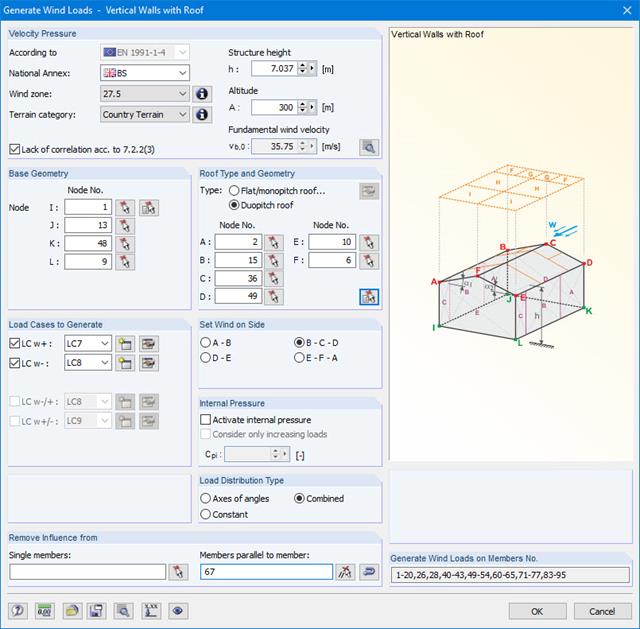
Obciążenia wiatrem mogą być automatycznie generowane jako obciążenia prętów na następujących elementach konstrukcyjnych (opcjonalnie z ciśnieniem wewnętrznym w przypadku budynków otwartych):
- Ściany pionowe
- Dachy płaskie
- Dachy jednospadowe
- Dachy dwuspadowe/korytowe
- Ściany pionowe wraz z dachem
Dostępne są poniższe normy:
-
EN 1991-1-3 (wraz z załącznikami krajowymi)
-
DIN 1055-4
-
CTE DB-SE-AE
-
ASCE/SEI 7-16
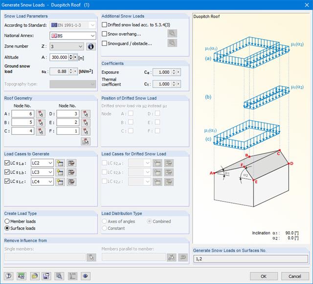
Generator obciążenia śniegiem może generować obciążenia śniegiem jako obciążenia prętowe lub obciążenia powierzchniowe.
Dodatkowe obciążenia śniegiem takie jak obciążenia śniegiem naniesionym, nasypem śnieżnym i barierkami przeciwśniegowymi mogą zostać również uwzględnione.
Dostępne są poniższe normy:
-
EN 1991-1-3 (wraz z załącznikami krajowymi)
-
DIN 1055-5
-
CTE DB-SE-AE
-
ASCE/SEI 7-16
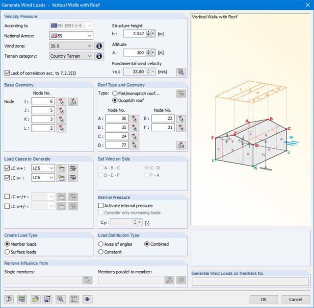
Obciążenia wiatrem mogą być automatycznie generowane jako obciążenia prętów lub obciążenia powierzchniowe na następujących elementach konstrukcyjnych (opcjonalnie z ciśnieniem wewnętrznym w przypadku budynków otwartych):
- Ściany pionowe
- Dachy płaskie
- Dachy jednospadowe
- Dachy dwuspadowe/korytowe
- Ściany pionowe wraz z dachem
Dostępne są poniższe normy:
-
EN 1991-1-3 (wraz z załącznikami krajowymi)
-
DIN 1055-4
-
CTE DB-SE-AE
-
ASCE/SEI 7-16