106 Wyniki
Wyświetl wyniki:
Sortuj według:

W rozszerzeniu Połączenia stalowe można używać nie tylko zwykłych typów prętów 'Belka', 'Kratownica' itd., ale także typu pręta 'Belka wynikowa' oraz przekroje z elementów powierzchniowych. Należy wybrać odpowiedni przekrój dla belki wynikowej, a następnie zdefiniować otwory prętowe w modelu powierzchniowym za pomocą edytora prętów.

Istnieje możliwość wykluczenia obiektów, takich jak pręty, powierzchnie itp. z obliczeń według kombinacji obciążeń (KO)/kombinacji wyników (KW). Dane te można wprowadzić w tabeli w zakładce 'Obiekty do wykluczenia'. Pozwala to na wymiarowanie określonych obiektów tylko przy użyciu określonych kombinacji obciążeń. Opcja ta jest dostępna we wszystkich rozszerzeniach z wyjątkiem rozszerzenia 'Połączenia stalowe'.

W przypadku obiektów obliczeniowych można opcjonalnie wyświetlić wygięcia lub wyniki ekstremalne.

Komponent "Płyta podstawy" umożliwia wymiarowanie połączeń z płytą podstawy za pomocą kotew zabetonowanych. Analizie poddawane są płyty, spoiny, zakotwienia oraz interakcja stal - beton.
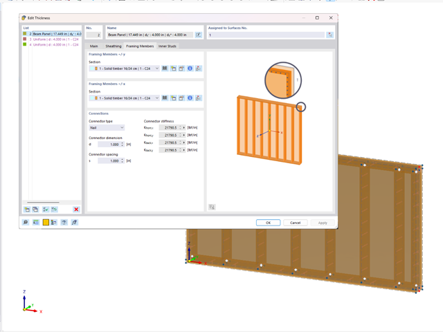
Za pomocą typu grubości "Panel belkowy" można modelować drewniane panele szkieletowe w przestrzeni 3D. Wystarczy określić geometrię powierzchni, a drewniane panele szkieletowe zostaną wygenerowane za pomocą wewnętrznej konstrukcji pręt-powierzchnia, wraz z symulacją elastyczności połączenia. Typ grubości płyty bel jest definiowany za pomocą rozszerzenia Powierzchnie wielowarstwowe.
„Panel belkowy” ma następujące zalety:
- Możliwe jest jednostronne i dwustronne poszycie
- Automatyczne obliczanie połączenia półsztywnego
- Poszycie z deskowania
- Poszycie spięte klamrami
- Poszycie zdefiniowane przez użytkownika
- Przedstawienie w postaci całego geometrycznego obiektu 3D (rama, przewiązanie poprzeczne, słup, poszycie, zszywki) wraz z mimośrodem
- Uwzględnianie otworów za pomocą komórek powierzchni
- Wymiarowanie elementów konstrukcyjnych z wykorzystaniem rozszerzenia Projektowanie konstrukcji drewnianych
- Niezależnie od materiału (np. płyta gipsowo-kartonowa z profilami formowanymi na zimno i płyty gipsowo-włóknowe jako poszycie)

- 002687
- Ogólne informacje
- Projektowanie konstrukcji drewnianych RFEM 6
- Projektowanie konstrukcji drewnianych RSTAB 9
Rozszerzenie Projektowanie konstrukcji drewnianych dla programu RFEM 6/RSTAB 9 ma wiele zastosowań i łączy w sobie wiele dodatkowych elementów. [*S16332764*] Rozszerzenie Wymiarowanie drewna dla RFEM 6

Rozszerzenie Projektowanie konstrukcji betonowych umożliwia wymiarowanie prętów i powierzchni ze względu na zmęczenie zgodnie z EN 1992-1-1, rozdział 6.8.
W przypadku obliczeń zmęczenia można opcjonalnie wybrać dwie metody lub poziomy obliczeniowe w konfiguracjach obliczeniowych:
- Poziom obliczeniowy 1: Obliczenia uproszczone wg. do 6.8.6 i 6.8.7(2) Kryterium uproszczone jest stosowane dla częstych kombinacji oddziaływań zgodnie z EN 1992-1-1, rozdział 6.8.6 (2) oraz EN 1990, równ. (6.15b) wraz z obciążeniami od ruchu drogowego w stanie użytkowalności. Dla stali zbrojeniowej sprawdzany jest maksymalny zakres naprężeń zgodnie z 6.8.6. Naprężenie ściskające w betonie jest określane za pomocą górnego i dolnego dopuszczalnego naprężenia zgodnie z 6.8.7(2).
- Poziom analizy 2: Obliczanie równoważnego naprężenia niszczącego zgodnie z 6.8.5 i 6.8.7(1) (uproszczone obliczenia na zmęczenie): Obliczenia z wykorzystaniem zakresów równoważnych naprężeń niszczących są przeprowadzane dla kombinacji zmęczeniowych, zgodnie z EN 1992-1-1, rozdział 6.8.3, równ. (6.69) o specyficznie zdefiniowanym oddziaływaniu cyklicznym Qfat .

W rozszerzeniu Projektowanie konstrukcji stalowych można przeprowadzić kontrolę obliczeń stateczności i przekrojów profili formowanych na zimno według EN 1993-1-3, zgodnie z punktami 6.1.2 - 6.1.5 i 6.1.8 - 6.1.10.
Przejdź do filmu
W rozszerzeniu „Połączenia stalowe” można uwzględnić naprężenie wstępne śrub w obliczeniach dla wszystkich komponentów. Sprężenie można łatwo aktywować za pomocą pola wyboru w parametrach śruby i ma ono wpływ zarówno na analizę naprężeniowo-odkształceniową, jak i na analizę sztywności.
Śruby sprężone to specjalne śruby stosowane w konstrukcjach stalowych w celu wygenerowania dużej siły zaciskowej między połączonymi elementami konstrukcyjnymi. Ta siła docisku powoduje tarcie między elementami konstrukcyjnymi, co umożliwia przenoszenie sił.
Funkcjonalność
Śruby sprężane są dokręcane z określonym momentem, co powoduje ich rozciąganie i powstawanie siły rozciągającej. Ta siła rozciągająca jest przenoszona na połączone elementy i prowadzi do powstania dużej siły mocującej. Siła zaciskowa zapobiega poluzowaniu połączenia i zapewnia niezawodne przenoszenie siły.
Zalety
- Wysoka nośność: Śruby wstępnie rozciągane mogą przenosić duże siły.
- Niskie odkształcenie: Minimalizują odkształcenie połączenia.
- Wytrzymałość zmęczeniowa: Są odporne na zmęczenie.
- Łatwość montażu: Są one stosunkowo łatwe w montażu i demontażu.
Analiza i wymiarowanie
Obliczenia śrub sprężanych są przeprowadzane w RFEM z wykorzystaniem modelu analitycznego ES wygenerowanego przez rozszerzenie "Połączenia stalowe". Uwzględnia ona siłę zwarcia, tarcie między elementami konstrukcyjnymi, wytrzymałość śrub na ścinanie oraz nośność elementów konstrukcyjnych. Wymiarowanie odbywa się zgodnie z DIN EN 1993-1-8 (Eurokod 3) lub amerykańską normą ANSI/AISC 360-16. Utworzony model analityczny wraz z wynikami można zapisać i wykorzystać jako niezależny model w programie RFEM.

Teraz w rozszerzeniu Projektowanie konstrukcji betonowych można wymiarować elementy wykonane z betonu zbrojonego włóknami zgodnie z wytyczną "DAfStb Steel Fiber-Reinforced Concrete".
Ta opcja jest dostępna dla obliczeń zgodnie z EN 1992-1-1. Obliczenia zgodnie z wytyczną DAfStb są przeprowadzane po przypisaniu betonu typu "Fibrobeton" do elementu konstrukcyjnego z betonu zbrojonego.
Przejdź do filmu
W rozszerzeniu Projektowanie konstrukcji betonowych można wymiarować dowolny przekrój RSECTION. Otulinę betonową, zbrojenie na ścinanie i zbrojenie podłużne definiuje się bezpośrednio w RSECTION.
Po zaimportowaniu przekroju ze zbrojeniem RSECTION do programu RFEM 6, można go również wykorzystać do obliczeń w rozszerzeniu Projektowanie konstrukcji betonowych.
Przejdź do filmu
W programach RFEM i RSTAB można wymiarować pręty przy użyciu materiału typu "Fornir klejony warstwowo". Dostępni są następujący producenci:
- Pollmeier (Baubuche)
- Metsä (kerto LVL)
- STEICO
- Stora Enso
W konfiguracji stanu granicznego nośności można uwzględnić współczynniki wytrzymałości w celu zwiększenia wytrzymałości. Niezależnie od tego współczynniki zmniejszające wytrzymałości są uwzględniane automatycznie. Wypróbuj teraz!
Przejdź do filmu
Wymiarowanie prętów stalowych formowanych na zimno zgodnie z AISI S100-16/CSA S136-16 jest dostępne w RFEM 6. Dostęp do obliczeń można uzyskać, wybierając normy „AISC 360” lub „CSA S16” w rozszerzeniu Projektowanie konstrukcji stalowych. Następnie dla obliczeń elementów formowanych na zimno automatycznie wybierane jest „AISI S100” lub „CSA S136”.
Do obliczania sprężystego obciążenia wyboczeniowego pręta program RFEM stosuje metodę DSM. Bezpośrednia metoda wytrzymałości oferuje dwa typy rozwiązań, numeryczne (metoda pasm skończonych) i analityczne (specyfikacja). Krzywą charakterystyczną (sygnaturę) FSM i kształty wyboczenia można wyświetlić w oknie dialogowym Przekroje.

Rozszerzenie Połączenia stalowe umożliwia wymiarowanie połączeń prętów o złożonych przekrojach. Ponadto można przeprowadzać obliczenia połączeń dla prawie wszystkich przekrojów cienkościennych z biblioteki programu RFEM.
Przejdź do filmu
W rozszerzeniu Połączenia stalowe można wymiarować połączenia zgodnie z amerykańską normą ANSI/AISC 360-16. Zintegrowane zostały następujące metody obliczeń:
- Obliczenia współczynnika obciążenia i odporności (LRFD)
- Projektowanie dopuszczalnych naprężeń (ASD)

Rozszerzenie Projektowanie konstrukcji drewnianych dla RFEM umożliwia wymiarowanie prętów i powierzchni zgodnie z Eurokodem 5, SIA 265 (norma szwajcarska), CSA O86 (norma kanadyjska) lub ANSI/AWC NDS (norma amerykańska), np. drewno klejone krzyżowo, drewno klejone warstwowo, drewno iglaste, materiały drewnopochodne itp.
Przejdź do filmu
Istniejące zbrojenie powierzchniowe można automatycznie zaprojektować tak, aby pokryć wymagane zbrojenie. Można wybrać, czy automatycznie ma być definiowana średnica zbrojenia, czy też rozstaw prętów.
Przejdź do filmu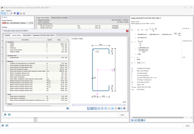
Chcesz przeprowadzić kontrolę przekrojów prętów stalowych zimnogiętych zgodnie z EN 1993-1-3? Niezależnie od tego, czy są to profile zimnogięte z biblioteki przekrojów, czy też przekroje ogólne formowane na zimno (nieperforowane) z RSECTION, program do analizy statyczno-wytrzymałościowej pomoże w definiowaniu przekroju efektywnego z uwzględnieniem wyboczenia lokalnego i niestateczności. Można również przeprowadzić kontrolę przekroju zgodnie z EN 19 93 1 3, sekcja 6 1 6. W takim przypadku siły wewnętrzne z obliczeń z wykorzystaniem Skręcania skrępowanego (7 stopni swobody) są uwzględniane za pomocą kontroli naprężeń zastępczych
Przejdź do filmu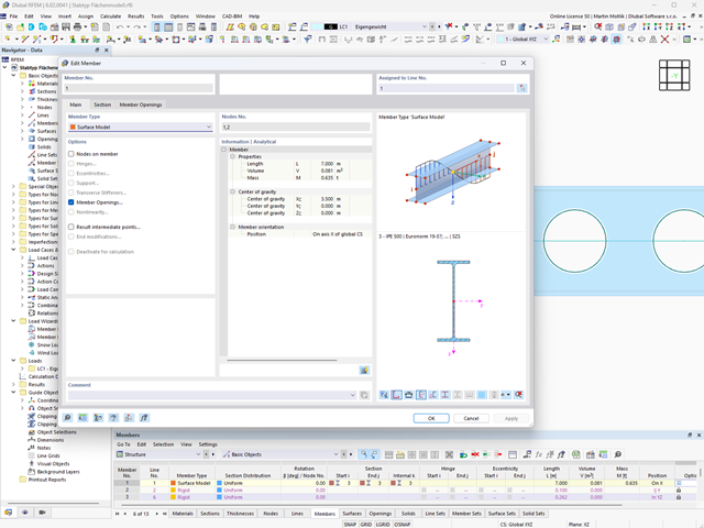
Potrzebujesz pomocy? Typ pręta "model powierzchniowy" pomaga w symulacji pręta jako modelu powierzchniowego w modelu ogólnym.
Ta funkcja zapewnia:
- Szybkie wprowadzanie poprzez pręt z przekrojem
- Symulację otworów w środniku
- Jednoczesne wyprowadzanie wyników dla pręta i powierzchni
- Wymiarowanie wyników prętów w rozszerzeniu
- Uwzględnienie rzeczywistego rozkładu naprężeń
Pręt powierzchniowy można wykorzystać między innymi w następujących zastosowaniach:
- Belki ażurowe
- Belki perforowane
- Belka z otworami prostokątnymi
- Kratownica Vierendeela
- 002496
- Ogólne informacje
- Projektowanie konstrukcji drewnianych RFEM 6
- Projektowanie konstrukcji drewnianych RSTAB 9
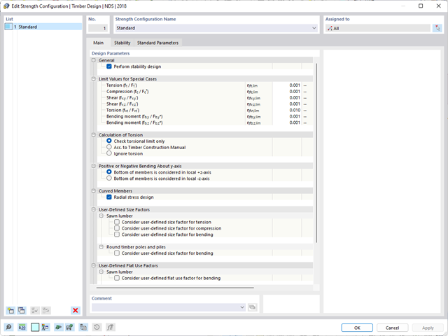
Występuje skręcanie? W takim przypadku to Ty decydujesz o sposobie przeprowadzenia obliczeń. Do dyspozycji masz następujące opcje:
- Zezwól na dalsze obliczenia, jeżeli naprężenie styczne od skręcania nie przekracza wartości granicznej
- Wymiarowanie zgodnie z Timber Construction Manual, 4.6
- Ignorowanie skręcania

- 002469
- Ogólne informacje
- Projektowanie konstrukcji betonowych RFEM 6
- Projektowanie konstrukcji betonowych RSTAB 9
Pracujesz z elementami konstrukcyjnymi składającymi się z płyt? W takim przypadku należy przeprowadzić obliczenia na ścinanie z uwzględnieniem wymagań obliczania przebicia, na przykład zgodnie z 6.4, EN 1992-1-1. Oprócz płyt stropowych można w ten sposób wymiarować również płyty fundamentowe.
W konfiguracji stanu granicznego nośności dla wymiarowania betonu można zdefiniować parametry obliczeń przebicia dla wybranych węzłów.

- 002464
- Wyniki
- Projektowanie konstrukcji aluminiowych RFEM 6
- Projektowanie konstrukcji aluminiowych RSTAB 9
Jak zwykle, wprowadzasz układ i obliczasz siły wewnętrzne w programach RFEM i RSTAB. Masz nieograniczony dostęp do obszernych bibliotek materiałów i przekrojów. Czy wiesz, że za pomocą programu RSECTION można tworzyć przekroje ogólne? Oszczędza to dużo pracy.
Nie bój się'dodatkowych okien i chaosu przy wprowadzaniu danych! Dzieje się tak, ponieważ wymiarowanie aluminium jest w pełni zintegrowane z programami głównymi i automatycznie uwzględnia konstrukcję oraz istniejące wyniki obliczeń. Dalsze dane wejściowe dla obliczeń aluminium, takie jak długości efektywne, redukcje przekroju lub parametry obliczeniowe, można przypisać bezpośrednio do projektowanych obiektów. W wielu miejscach programu najlepiej jest użyć funkcji [Wskaż] do wyboru grafiki - w prosty i efektywny sposób.

Wymiarowanie połączenia ramy o prętach zbieżnych i usztywnionych. Dla połączenia przeprowadzono analizę naprężeń i stateczności przy wyboczeniu. Aby wyświetlić wyniki dla wyboczenia, połączenie zostało przekształcone w osobny model.

- 002133
- Ogólne informacje
- Projektowanie konstrukcji drewnianych RFEM 6
- Projektowanie konstrukcji drewnianych RSTAB 9
- Szeroki wybór przekrojów, takich jak przekroje prostokątne, kwadratowe, teowe, okrągłe, złożone, nieregularne przekroje parametryczne i wiele innych (przydatność do obliczeń zależy od wybranej normy)
- Wymiarowanie drewna klejonego krzyżowo (CLT)
- Wymiarowanie materiałów drewnopochodnych i drewna klejonego warstwowo zgodnie z EC 5
- Wymiarowanie prętów o zmiennym przekroju (metoda zgodna z normą)
- Możliwe jest dostosowanie istotnych współczynników obliczeniowych i parametrów normowych
- Elastyczność dzięki szczegółowym opcjom ustawień dla podstawy i zakresu obliczeń
- Szybkie i przejrzyste wyświetlanie wyników dla globalnej oceny ich rozkładu na konstrukcji po zakończeniu obliczeń
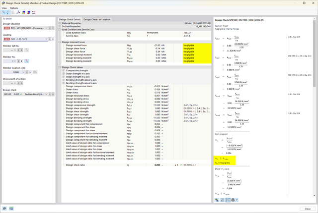
- Szczegółowe wyniki obliczeń i niezbędne wzory (jasna i łatwa do zweryfikowania ścieżka wyników)
- Przejrzyste zestawienie wyników w formie numerycznej w stosownych oknach oraz możliwość ich graficznego przedstawienia na konstrukcji
- Integracja wyników z protokołem wydruku programu RFEM/RSTAB
- 002134
- Ogólne informacje
- Projektowanie konstrukcji drewnianych RFEM 6
- Projektowanie konstrukcji drewnianych RSTAB 9
- Wymiarowanie elementów rozciąganych, ściskanych, zginanych, ścinanych, skręcanych i poddanych połączonemu działaniu tych sił wewnętrznych
- Uwzględnienie podcięcia
- Obliczanie ściskania prostopadle do włókien na podporach końcowych i pośrednich z (EC 5) i bez elementów wzmacniających (śruby z pełnym gwintem)
- Opcjonalna redukcja siły tnącej na podporze
- Wymiarowanie prętów zakrzywionych i zbieżnych
- Uwzględnianie wyższych wytrzymałości dla podobnych elementów, które znajdują się blisko siebie (współczynnik ksys wg EN 1995-1-1, 6.6(1)-(3))
- Możliwość zwiększenia nośności na ścinanie dla drewna iglastego zgodnie z DIN EN 1995‑1‑1:NA NDP do 6.1.7(2)
- 002135
- Obliczenia
- Projektowanie konstrukcji drewnianych RFEM 6
- Projektowanie konstrukcji drewnianych RSTAB 9
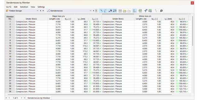
- Analiza stateczności dla wyboczenia giętnego, wyboczenia skrętnego i wyboczenia giętno-skrętnego przy ściskaniu
- Import długości efektywnych z obliczeń przy użyciu rozszerzenia Stateczność konstrukcji
- Graficzne wprowadzanie i kontrola zdefiniowanych podpór węzłowych oraz długości efektywnych w celu analizy stateczności
- Określanie długości zastępczych prętów o zbieżnym przekroju
- Uwzględnienie położenia stężenia zwichrzenia
- Analiza zwichrzenia elementów poddanych obciążeniu momentem
- W zależności od normy istnieje wybór między wprowadzaniem wartości Mcr przez użytkownika, metodą analityczną z normy lub wykorzystaniem wewnętrznego solwera wartości własnych
- Uwzględnienie panelu usztywniającego i ograniczenia obrotu podczas korzystania z solwera wartości własnych
- Graficzne przedstawienie postaci własnej w przypadku zastosowania solwera wartości własnych
- Analiza stateczności elementów konstrukcyjnych ze ściskaniem i naprężeniem zginającym, w zależności od normy obliczeniowej
- Przejrzyste obliczenia wszystkich niezbędnych współczynników, takich jak współczynniki uwzględniające rozkładu momentów lub współczynniki interakcji
- Alternatywne uwzględnienie wszystkich wpływów dla analizy stateczności podczas określania sił wewnętrznych w programie RFEM/RSTAB (analiza drugiego rzędu, imperfekcje, redukcja sztywności, ewentualnie w połączeniu z rozszerzeniem Skręcanie skrępowane (7 stopni swobody))

- 002372
- Ogólne informacje
- Projektowanie konstrukcji drewnianych RFEM 6
- Projektowanie konstrukcji drewnianych RSTAB 9
- Dowolna definicja czasu zwęglania
- W przypadku konstrukcji powierzchniowych (drewno klejone krzyżowo) można obliczyć z przyczepnością lub bez
- Bezpłatna, zdefiniowana przez użytkownika specyfikacja parametrów pożaru
- Uwzględnienie różnych długości efektywnych do obliczania odporności ogniowej
- Opcjonalne obliczenia dla 'ściskania w poprzek włókien'
- Zintegrowane z RFEM/RSTAB graficzne wyświetlanie wyników, np. B. Stopień wykorzystania
- Pełna integracja wyników z protokołem wydruku programu RFEM/RSTAB
- 002373
- Ogólne informacje
- Projektowanie konstrukcji drewnianych RFEM 6
- Projektowanie konstrukcji drewnianych RSTAB 9
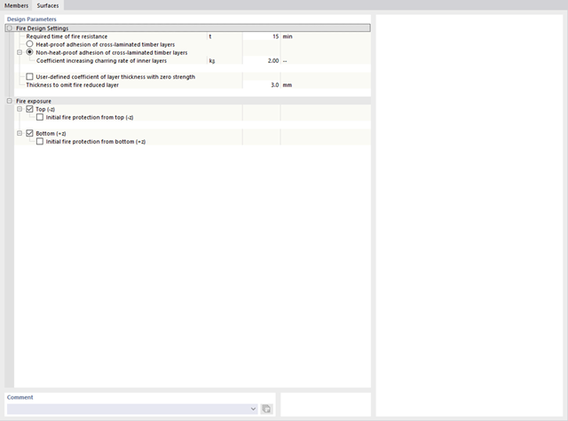
Program RFEM/RSTAB oferuje również szereg funkcji na wypadek pożaru. Program umożliwia automatyczne generowanie kombinacji obciążeń i wyników dla wyjątkowej sytuacji obliczeniowej w obliczeniach odporności ogniowej. Pręty, które mają zostać zwymiarowane wraz z odpowiednimi siłami wewnętrznymi, są importowane bezpośrednio z programu RFEM/RSTAB. Przechowywane są również wszystkie informacje o materiale i przekroju. Nie musisz'robić nic więcej.
Parametry istotne dla obliczeń odporności ogniowej można definiować poprzez przypisanie konfiguracji odporności ogniowej do obliczanych prętów i powierzchni. Ponadto można wprowadzić dalsze szczegółowe ustawienia, takie jak zdefiniowanie ekspozycji na ogień z jednej strony aż po wszystkie strony.
- 002374
- Ogólne informacje
- Projektowanie konstrukcji drewnianych RFEM 6
- Projektowanie konstrukcji drewnianych RSTAB 9
Jak zapewne wiesz, weryfikacje są przeprowadzane dla wybranych prętów z uwzględnieniem zdefiniowanego czasu zwęglania. Wszystkie niezbędne współczynniki i współczynniki redukcyjne są zapisywane w programie i uwzględniane przy określaniu nośności konstrukcji. Pozwala to zaoszczędzić dużo pracy.
Długości efektywne dla obliczeń pręta zastępczego są pobierane bezpośrednio z danych dotyczących wytrzymałości. Nie trzeba ich ponownie wprowadzać.
Po zakończeniu obliczeń program wyświetla w przejrzysty sposób obliczenia odporności ogniowej ze wszystkimi szczegółami wyników. Pozwala to na przejrzyste śledzenie wyników. Wyniki zawierają również wszystkie wymagane parametry, dzięki czemu można określić temperaturę elementu w czasie projektowania.
Oprócz wszystkich tych funkcji, program umożliwia zintegrowanie wszystkich tabel wyników i grafik, w tym wyników stanu granicznego nośności i użytkowalności, z globalnym protokołem wydruku programu RFEM/RSTAB, jako część wyników obliczeń stali.
- 002375
- Ogólne informacje
- Projektowanie konstrukcji drewnianych RFEM 6
- Projektowanie konstrukcji drewnianych RSTAB 9
W przypadku obliczeń zgodnie z Eurokodem 5 parametry załączników krajowych (NA) są zintegrowane dla następujących krajów:
-
 DIN EN 1995-1-1/NA:2014-07 (Niemcy)
 -
 ÖNORM EN 1995-1-1/NA:2019-06 (Austria)
 -
 SN EN 1995-1-1/NA:2015-03 (Szwajcaria)
 -
 BDS EN 1995-1-1/NA:20157-06 (Bułgaria)
 -
 BS EN 1995-1-1/NA:2019-09 (Wielka Brytania)
 -
 CEN EN 1995-1-1/2014-05 (Unia Europejska)
 -
 CYS EN 1995-1-1/NA:2019-06 (Cypr)
 -
 CZE EN 1995-1-1/NA:2015-05 (Republika Czeska)
 -
 DS EN 1995-1-1/NA:2019-09 (Dania)
 -
 ELOT EN 1995-1-1/NA:2010-01 (Grecja)
 -
 EVS EN 1995-1-1/NA:2015-11 (Estonia)
 -
 HRN EN 1995-1-1/NA:2015-03 (Chorwacja)
 -
 I S. EN 1995-1-1/NA:2014-05 (Irlandia)
 -
 ILNAS EN 1995-1-1/NA:2020-3 (Luksemburg)
 -
 IST EN 1995-1-1/NA:2014-09 (Islandia)
 -
 LST EN 1995-1-1/NA:2014-06 (Litwa)
 -
 LVS EN 1995-1-1/NA:2014-12 (Łotwa)
 -
 MSZ EN 1995-1-1/NA:2015-06 (Węgry)
 -
 NBN EN 1995-1-1/NA:2014-06 (Belgia)
 -
 NEN EN 1995-1-1/NA:2014-06 (Holandia)
 -
 NF EN 1995-1-1/NA:2020-04 (Francja)
 -
 NP EN 1995-1-1/NA:2014-09 (Portugalia)
 -
 NS EN 1995-1-1/NA:2014-08 (Norwegia)
 -
 PN EN 1995-1-1/NA:2014-07 (Polska)
 -
 SFS EN 1995-1-1/NA:2016-12 (Finlandia)
 -
 SIST EN 1995-1-1/NA:2018-01 (Słowenia)
 -
 SR EN 1995-1-1/NA:2014-12 (Rumunia)
 -
 SS EN 1995-1-1/NA:2018-02 (Singapur)
 -
 SS EN 1995-1-1/NA:2014-05 (Szwecja)
 -
 STN EN 1995-1-1/NA:2019-12 (Słowacja)
 -
 TKP EN 1995-1-1/NA:2019-09 (Białoruś)
 -
 UNE EN 1995-1-1/NA:2016-04 (Hiszpania)
 -
 UNI EN 1995-1-1/NA:2016-11 (Włochy)