


.png?mw=1040&hash=2ea753d2cebf484b74450d6ce89cea2864b6f346)


The "Steel Joints" add-on uses EN 1993-1-8 (Eurocode 3 including National Annexes), ANSI/AISC 360-22, and CSA S16 for the design of steel connections. Additional standards will follow.
 Add-on "Steel Joints"
Online Manuals


Why use two structural analysis programs if one is enough?
Optimize your steel connection analysis and design with RFEM and the "Steel Joints" add-on. This powerful all-in-one solution avoids error-prone and time-consuming data imports, such as the transfer of members, eccentricities, and load combinations. Take advantage of automatic and seamless updates of your calculations with every model change – efficiently and all from a single source.
Increase the efficiency and accuracy of your modeling and design of steel connections.
- Efficiency improvement: No data import or export is necessary, which saves you time and money
- Automated updates in case of changes of the structure
- Maximum transparency due to a completely visible and customizable submodel
- Ultimate flexibility due to ready-made and customizable templates
- High-quality 3D visualization for impressive presentations of the joint model as well as the individual joints in the entire model
- Precise measuring and dimensioning functions for the joint component points
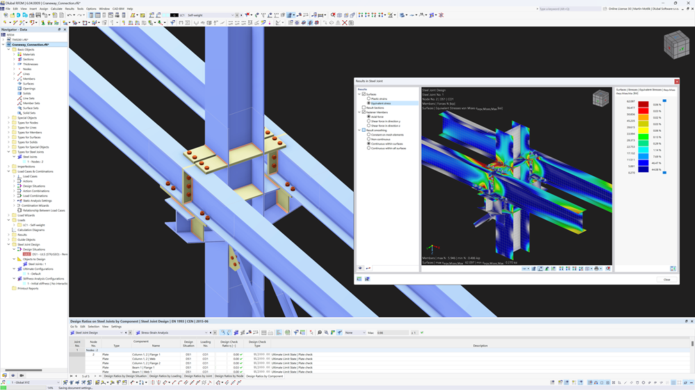
 Video: FE-Based Analysis and Design of Steel Connections
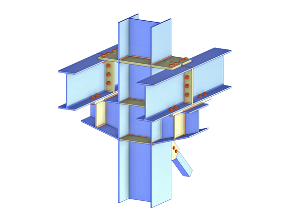
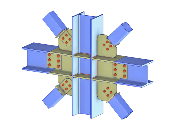
 Add-on "Steel Joints for RFEM 6" | Component Library
 Base Plate Connection with Cast-in Anchors | Results of Contact Stresses in Base Plate
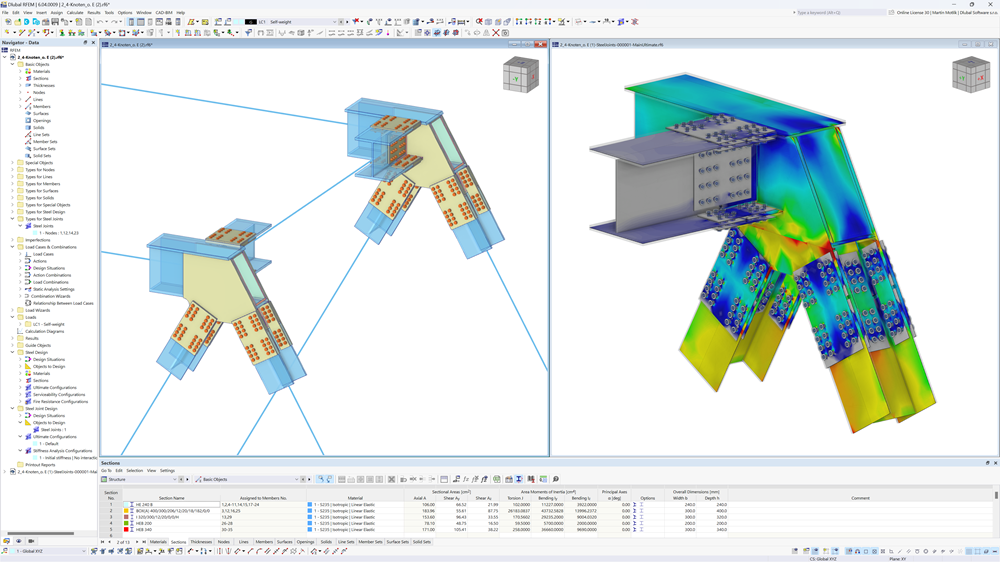
 RFEM: Steel Connections of Truss Bridge and FE Model with Results
Video: FE-Based Analysis and Design of Steel Connections
Main Features of "Steel Joints" Add-on
Key Features of Steel Joints Add-on


Models to Download | Add-on "Steel Joints"
Design of Steel Joints According to International Standards
Currently Supported Standards in “Steel Joints” Add-on


.png?mw=200&hash=ceabdac71454991b172d1a40faa3844b9a756ff1)
Calculate Your Price
.png?mw=400&hash=3145b148921d52f0f0d5df04b4aaa44675fd0212)
Total Amount 3,080.00 USD


