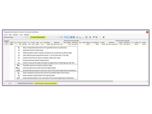
The seismic design result is categorized into two sections: member requirements and connection requirements.
The "Seismic Requirements" include the Required Flexural Strength and the Required Shear Strength of the beam-to-column connection for moment frames. They are listed in the ‘Moment Frame Connection by Member’ tab. For braced frames, the Required Connection Tensile Strength and the Required Connection Compressive Strength of the brace are listed in the ‘Brace Connection by Member’ tab.
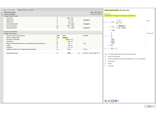
The program provides the performed design checks in tables. The design check details clearly display the formulas and references to the standard.


.png?mw=350&hash=b2324c4db119938012b5490afaa56e9aa826cdcc)


.png?mw=600&hash=49b6a289915d28aa461360f7308b092631b1446e)


