


Membrane structures are one of the current trends in civil engineering. They are characterized by their expressive shapes, lightness, and efficient use of material. Due to the lack of bending stiffness, these structures have an inseparable shape from the stress state.
This leads to the need to search for their shapes, which cannot be chosen arbitrarily. These structures with different shapes are made of fabric or foil. The cutting patterns are formed from planar material strips, and you achieve the intended structure by connecting and stretching them in the final position. The determination of cutting patterns is a sensitive step in the planning process, and its quality strongly influences the quality of the entire structure.
This article deals in detail with the two main processes - the shape determination of membrane structures, and the determination of cutting patterns. Special attention is paid to practical and useful insights for planning.
Design of Membrane Structures
In this chapter, the physical principles of shape determination for membrane structures are described first. Furthermore, the feasibility of prestress required by the civil engineer is discussed. The text is then supplemented by practical examples to illustrate the considerations and theories.
The planning of membrane structures differs significantly from the usual practice. Since the materials used practically have only a tension resistance, the shape cannot be selected freely. It is not possible to separate the shape from the prestress. In this case, the aesthetic and physical aspects of buildings are basically connected.
The shape of a membrane structure is determined by the boundary conditions and the spatial equilibrium system. The form-finding process can be described by Equation (1) below. The equilibrium shape is found if the virtual work does not change (δW = 0); that is, if the sum of the virtual work performing the required prestress σ and the virtual work performing the external load p (positive pressure, self-weight) is equal to zero.
In the equation above, t represents the thickness of the material used, δê is the change in material deformation, and δu is the deformation over the surface of the structure Ω.
In addition to some theoretical problems to be solved, there is a fundamental problem. The main problem is that a preset prestress is assumed. However, it is generally excluded. The membrane structures have a double curvature (that is, the Gaussian curvature is not equal to zero), which is why they exclude a homogeneous orthotropic prestress. Theoretically, a state where there is a specific prestress value in the warp direction and a precise prestress value in the weft direction at each point of the membrane is almost impossible. The only exception is the isotropic prestress, which can be achieved if the shape is physically real under the given boundary conditions.
Thus, the prestress itself must be found. The aim of the process (form-finding) is not only to find an unknown shape for a given prestress, but also to search for an unknown shape for a generally unknown prestress. This prestress is approximated by a value specified by the civil engineer for the warp and weft directions. A number of methods have been developed for form-finding. If you use different programs for problem solving, you can obtain more or less different results for the same input data. Then, of course, the question arises as to which solution is the optimal one. Some examples of different structures and required prestresses are shown in the following text.
![Basic Shapes of Membrane Structures [1]](/en/webimage/009595/2419502/01-en-png-png.png?mw=760&hash=529108d5d0bcd0d53775f3faa50f1a9ef0d40418)
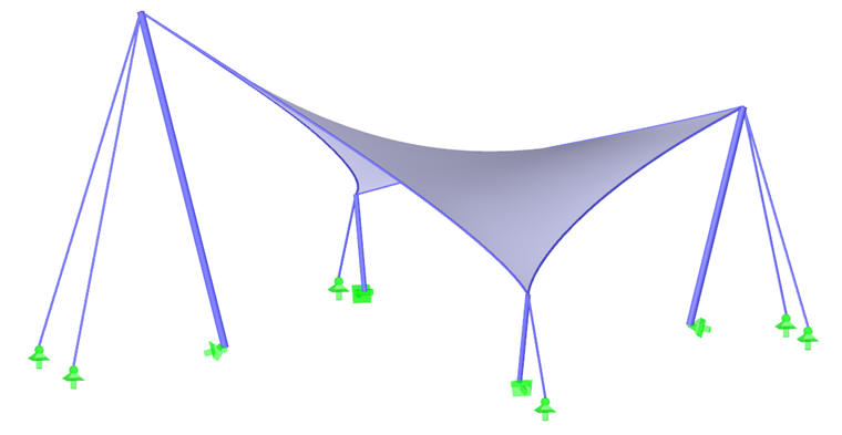
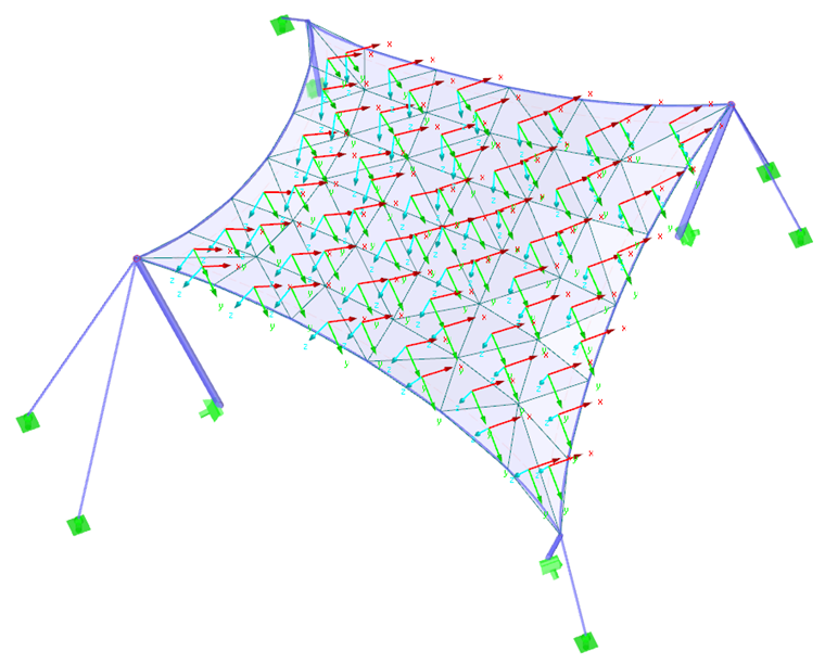
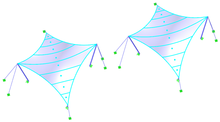
As a first example, we will use a hyperbolic paraboloid (Images 2 and 3). Both isotropic and orhotropic prestress are applied. For the isotropic prestress, two different results result from the form-finding process (Images 4 and 5), which are also commented upon briefly. The entered values for the isotropic prestress are nwarp = nweft = 2.00 kN/m. The perimeter cables have a relative sag of s = 8.00%. The results are displayed as vectors of the principal internal forces and a color scale.
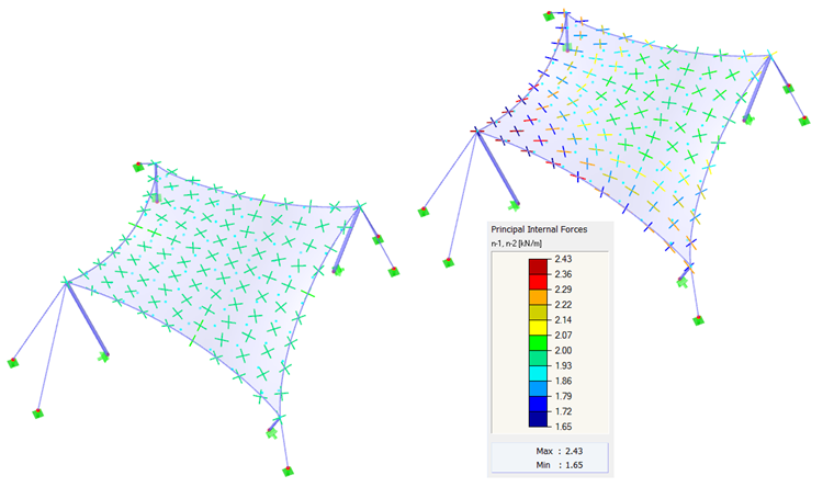
If two different results are obtained for the same input data, the question naturally arises as to which solution is the right one. In theory, both solutions are correct because both have reached an equilibrium state and both are feasible. However, the solution shown on the left shows a uniform prestress that is not concentrated on corner areas. Such local effects are considered as undesirable because they reduce the load-bearing capacity of the structure and result in uneven rheological effects. Therefore, the solution shown on the left is advantageous. Generally, it is considered as favorable to find a shape with a uniformly distributed and not locally concentrated prestress. The membrane structure is thus well prestressed, and its load-bearing capacity is not reduced in some areas by excessive prestress.
As already mentioned, an isotropic prestress is the only homogeneous prestress that can be achieved precisely. The achievable accuracy is practically limited only by the size of the FE mesh. In the case of a roughly set mesh, an equilibrium state cannot be approximated exactly, and thus the values may deviate from the entered prestresses. However, such deviations should be within a small range, and a coarser mesh does not necessarily lead to a clearly more concentrated prestress.
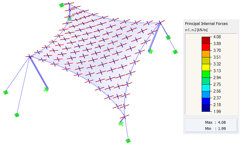
The same boundary conditions are applied for the other calculation. The prestress is defined as orthotropic with the values nwarp = 4.00 kN/m and nweft = 2.00 kN/m. The perimeter cables have a relative sag of s = 8.00%. As mentioned above, an exact homogeneous orthotropic prestress cannot be achieved, because this is not theoretically possible with double curvature of membrane structures. However, it is possible to obtain a shape with a prestress that approximates the specified values closely (Image 5). The result is thus uniformly distributed prestress approximating the input values. In the case of such a structure, there is no reason for any significant concentrations.
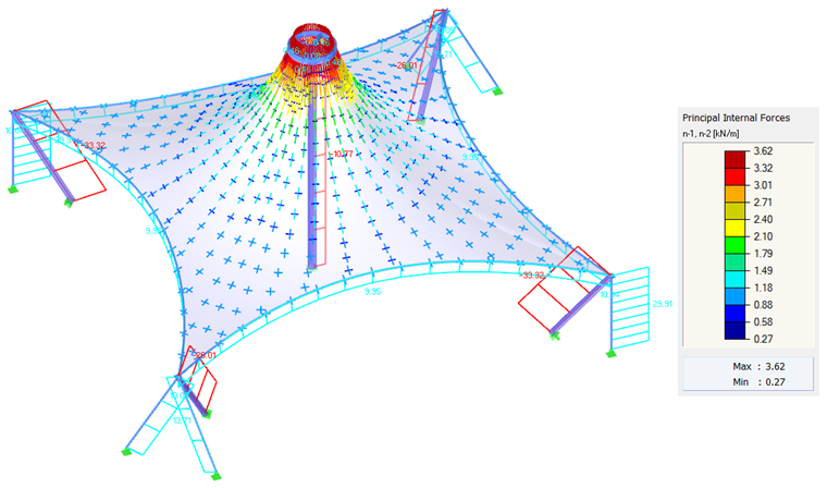
For most shapes, including hyperbolic paraboloids or arc-supported or pneumatic membranes (Image 1), the resulting prestress can be distributed evenly without the need for local prestress concentrations. For high conical shapes, it is not possible to avoid areas with concentrated prestress. Any concentrations occur at the apex of the cone, but they are neither necessary nor desired in the bottom corners (Image 6).
Whether a concentrated prestress is necessary or not can be deduced intuitively from the following formula (2). The equation represents an equilibrium of forces at a point where n1 and n2 are the principal internal forces, 1/R1 and 1/R2 are the curvatures in the direction of these principal internal forces, and p is any external load.
In the case of an anticlastic structure whose self-weight hardly influences the found shape, the equilibrium of forces in a node is given by the prestress and the curvatures in the opposite direction. The issue now is whether the curvature of the structure has to change so rapidly. If so, the locally concentrated prestress is inherent in the structure; otherwise, the prestress concentration is not necessary for the structure at all. This method can be applied to our examples. Shapes without conical areas (Images 4, 5, 8, and 10, except for the conical areas) do not require rapid changes in the curvature, which is why they can be prestressed uniformly. Conical areas show rapid changes of the radial and tangential curvatures, and therefore a quick change of the prestress cannot be avoided (Image 6 and conical areas in Image 10).
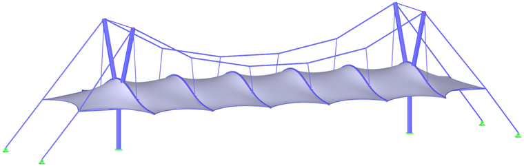
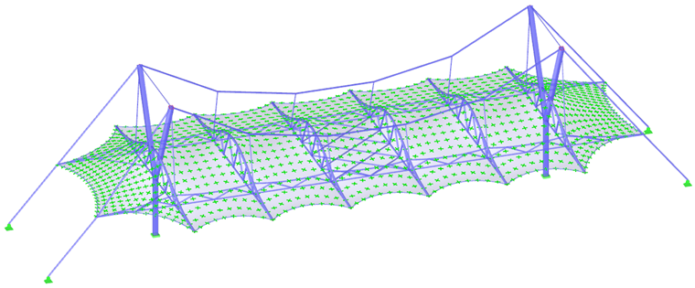
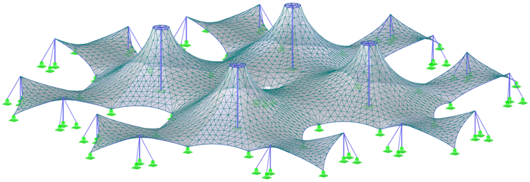
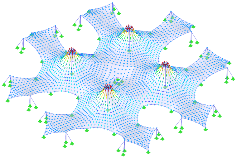
Two more complex structures (Images 7 and 9) and their prestresses (Images 8 and 10) are shown at the end of this chapter. In order to achieve the most possible accurate results in the form-finding process as well as in the structural analysis, the structure should be modeled as a whole and not separated into parts. Thus, the interaction of all parts of the structure and the force redistribution due to the deformations are considered.
Cutting Membrane Structures
The process of determining cutting patterns is explained in the following text. It describes the individual steps of the process, then presents a practical example to show how the material properties can affect the shapes of the cutting patterns.
As mentioned, the double curvature is one of the typical features of membrane structures, which is why its shape cannot be developed in one plane. However, the membranes are made of rolls of planar fabrics. For this, a cutting (that is, individual planar cutting patterns) must be generated that approximates their corresponding patterns in space. The process of creating a cutting pattern consists of two steps. First, the membrane structure is divided into individual spatial cutting patterns by means of cutting lines; then, the best possible approximation of planar cutting patterns to the spatial one is found.
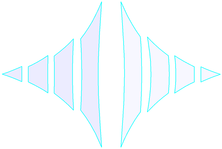
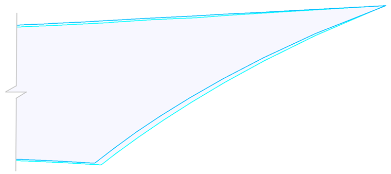
Theoretically, a membrane structure can be divided into partial strips by any cutting line. For practical reasons, however, geodetic cutting lines are usually used (Image 11, left), which are preferred because of the straight axis of the cutting patterns after flattening (Image 12, left). Plane sections (Image 11, right) that are not straight after flattening (Image 12, right) are used less often, and this results in a higher material requirement.
The second step of creating a cutting pattern is much more complex: finding the best possible approximation of a planar cutting pattern to the corresponding spatial cutting pattern. For this process, a number of methods were designed; the historically oldest used a simplified geometric method and the later methods, advanced mathematical mapping. The current methods are based on continuum mechanics, with a nonlinear analysis using the finite element method (FEM) for the determination of the cutting pattern.
The latter method is considered to be the most general solution for an approximation problem and allows you to consider the material properties of the fabric or film used. If you do not want to consider the orthotropic properties of the textile material or the transverse contraction, you can apply an isotropic material with the Poisson's ratio v = 0. However, if the material properties are to be included in the process of flattening the cutting pattern, the optimal shape of the cutting pattern can be achieved.
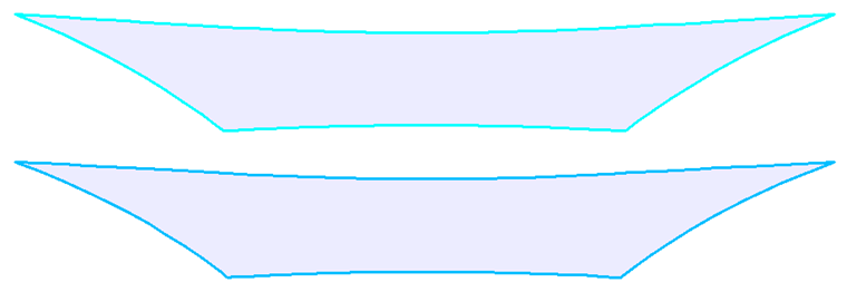
When testing the textile materials used for membrane structures, you usually determine the stiffnesses in the warp and weft directions and the Poisson's ratio. The shear stiffness is usually neglected. The following example shows how the shear stiffness affects the shape of the resulting cutting pattern. For the example, we have selected one of the middle cutting patterns of the hyperbolic paraboloid (Image 11). Two different materials are used for the cutting pattern.
The following values are provided for the first surface-treated fabric:
Ewarp = 1,600 kN/m
Eweft = 1,200 kN/m
vwarp/weft = 0.05
G = 400 kN/m
The other material, a textile mesh without surface treatment, has the following values:
Ewarp = 1,600 kN/m
Eweft = 1,200 kN/m
vwarp/weft = 0.05
G = 10 kN/m
The following image shows the resulting plane cutting patterns. By moving the centers of gravity of both cutting patterns into the same point and enlarging the right part of the cutting patterns in the cutout (Image 14), the difference between both shapes becomes clear. If you consider the material properties, you can achieve better quality cutting patterns. After assembling the structure, the real prestress is closer to the intended prestress.
For the determination of cutting patterns, a compensation is also used that is determined by biaxial tests and simulates the dissolution of the prestress in the fabric.
A nonlinear calculation according to the finite element method provides an energetically optimal planar cutting pattern in relation to the spatial one. Since it is based on physical principles, this calculation method is the most natural.
In the process of creating a cutting pattern, you can also consider other design requirements. Mainly, maintaining equal lengths of the adjacent edges of adjacent cutting patterns is required. Often, the application of different compensation is required for some edges of cutting patterns. This is often referred to as decompensation of the edges. In compliance with these design requirements and using the nonlinear analysis, an energetically optimized cutting pattern is found.
Conclusion
The aim of this article was to explain the main processes involved in planning membrane structures. The physical principles should be explained and the individual theses illustrated by examples. These examples were created in the engineering software RFEM by Dlubal Software GmbH [2].
Acknowledgments
This article was created with the support of the FAST-J-15-2803 project.
Authors
Ing. Rostislav Lang
doc. Ing. Ivan Němec, CSc.
Ing. Hynek Štekbauser
Institute of Structural Mechanics, BUT FCE Brno, FEM consulting Brno
Reviewer
Prof. Ing. Jiří Studnička, DrSc., Czech Technical University in Prague