Determining Effective Lengths
First, it is necessary to determine the effective lengths of the stub flanges according to Table 6.6. The bottom bolt row has barely an effect on the compression flange due to the very small lever arm, and is therefore neglected. Since both upper bolt rows are divided by the tension flange of the beam, the bolt rows must only be considered separately. Thus, you can avoid group failure of the bolt rows. The calculation of the effective lengths requires the parameters e, m, ex, mx, m2, bp, w.
![Parameters for Effective Lengths (Source: [1])](/en/webimage/009327/2418190/02-en-11-png.png?mw=760&hash=2af76ec88205c7fb526bac5773147ce40f214945)
For this example, the following values have been calculated:
In the case of the effective lengths, a distinction is made between circular and non-circular yield line patterns. The linear yield line pattern requires value α from Figure 6.11. The input values for this are based on the relation of the lever arms to the girder web (λ1) or to the girder flange (λ2) to the total width of the T-stub flange. The values for α between two diagrams in Figure 6.11 may be linearly interpolated.
![Determination of α-value (Source: [1])](/en/webimage/009328/2418192/03-en-7-png.png?mw=760&hash=7eefdea0637d8e2f11a9dcbfb0f912f77d53607c)
Using these input values, the effective lengths are determined according to Table 6.6 as follows.
Circular yield line pattern for the outer bolt row:
Circular yield line pattern for the inner bolt row:
leff,cp,i = 2 ∙ π ∙ 62.6 = 393.3 mm
Non-circular yield line pattern for the outer bolt row:
Non-circular yield line pattern for the inner bolt row:
leff,nc,i = 6.65 ∙ 62.6 = 416.3 mm
To determine the design resistance in Failure Mode 1, that is with pure flange yielding, the shorter length of both yield line patterns is used. When determining the design resistance in Failure Mode 2, that is bolt failure with simultaneous flange yielding, the non-circular yield line pattern can only occur.
This results in the following effective lengths.
Outer bolt row:
leff,1,a = 150 mm
leff,2,a = 150 mm
Inner bolt row:
leff1,i = 393.3 mm
leff2,i = 416.3 mm
Check if Prying Forces May Develop
Before the design resistance of the end plate in Failure Mode 1 is determined, it must be checked whether prying forces may develop. Since this allows you to achieve higher design resistance values, the dimensions and thickness of the grip package should always be chosen or changed in a way so that the equation Lb < Lb* is fulfilled. Lb is the bolt elongation length, taken equal to the grip length (total thickness of the material and washers), plus half the sum of the height of the bolt head and the height of the nut.
The grip length, assuming that a symmetrical beam joint is applied, results in:
Lb = 2 ∙ 25 + 2 ∙ 4 + 0.5 ∙ 19 + 0.5 ∙ 15 = 75 mm
Lb* must be determined separately for the outer and the inner bolt rows.
Outer bolt row:
Inner bolt row:
Therefore, prying forces may develop in both bolt rows.
Design Resistance of T-Stub Flanges
For the "complete yielding of the flange" failure mode, Method 1 of EN 1993-1-8 is used in this example. The tension resistance of both T-stub flanges is determined as follows.
"Bolt failure with yielding of the flange" failure mode:
Governing the Design Resistance of T-Stub Flanges
Failure Mode 2 governs for both bolt rows.
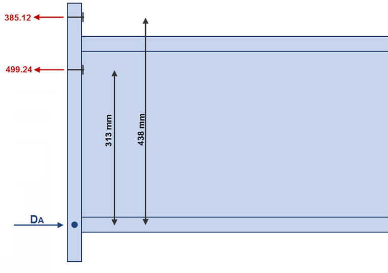
Outer bolt row: 385.12 kN
Inner bolt row: 499.24 kN
Moment Resistance of the Joint
The calculated design resistance values of the individual bolt rows now only have to be multiplied by the respective lever arm to the compression point.
The lever arms are
438 mm for the outer bolt row,
313 mm for the inner bolt row.
Thus, the design moment resistance of the joint results in
MRd = 385.12 ∙ 0.438 + 499.24 ∙ 0.313 = 324.95 kNm.
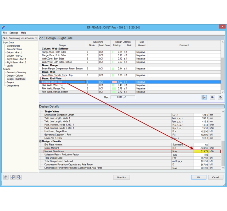
Comparison of Results
If this joint is calculated as a rigid frame joint in RF-/FRAME-JOINT Pro, the resulting design resistance of the end plate is 319.79 kNm. According to Typified Connections [2], the design resistance is 331.3 kNm, which corresponds relatively accurately to the manual calculation.