In contrast to RFEM 5, where you are asked to provide the input data for the modal analysis in the associated add-on module, the Modal Analysis add-on in RFEM 6 / RSTAB 9 is fully integrated into the program. You can use it to determine the lowest eigenvalues of the structure, and you can adjust the number of eigenvalues to be considered. You can also define several modal analyses (for example, when you want to analyze different masses or stiffness modifications).
Some features of the add-on are automatic consideration of masses from self-weight, direct import of masses from load cases or load combinations, and definition of additional masses, as well as neglecting masses of any object of the model. These and other features of the add-on will be discussed in more detail in the following text.
Importing Masses
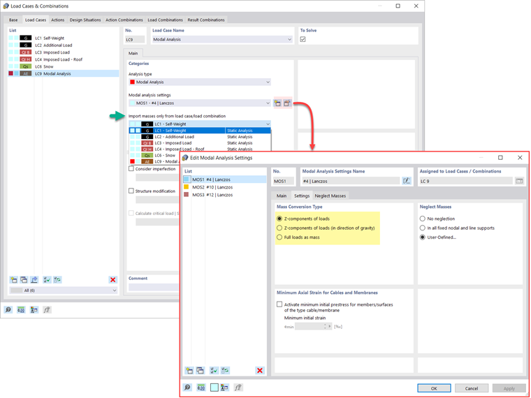
In RFEM 6, several options are at your disposal for defining masses for the modal analysis. Masses from self-weight are automatically considered, and you can consider loads and masses directly in the load case of the modal analysis type, as shown in Image 1. You also have the possibility to select whether to consider full loads as masses, load components in the global Z-direction, or only the load components in the direction of gravity.
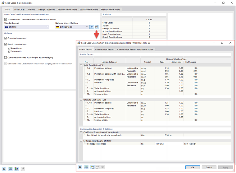
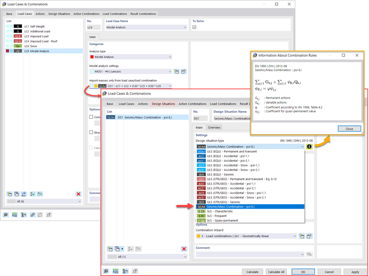
In addition, or as an alternative to the options for importing masses described above, you can manually define load combinations from which masses will be considered in the modal analysis. If you have selected a design code (Image 2), you can create a design situation with a seismic/mass combination type so that the program automatically calculates a mass situation for the modal analysis according to the preferred design code, as shown in Image 3.
In other words, the program creates a load combination based on the preset combination coefficients for the selected standard, which contains the masses to be used for the modal analysis.
Adding Masses
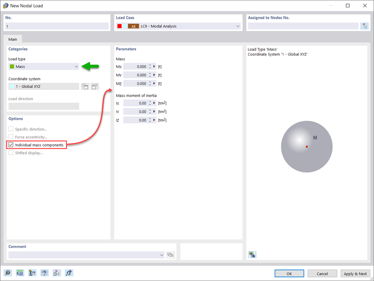
If you want to consider other loads as masses in addition to the static loads, you can do it for nodal, member, line, and surface loads in RFEM 6. This can be done by selecting Mass as a load type when defining the load of interest. For such loads, it is possible to define a mass or mass components in the X, Y, and Z directions. For nodal masses, you can also specify moments of inertia X, Y, and Z in order to model more complex mass points. This is shown in Image 4.
Neglecting Masses
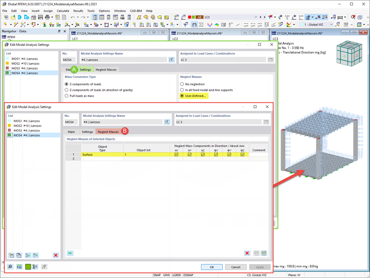
It is often necessary to neglect masses, especially when the output of the modal analysis is to be employed by the seismic analysis, where 90% of the effective modal mass in each direction is required for the calculation.
Thus, you can neglect masses in all fixed nodal and line supports so that the program will automatically deactivate masses associated with them, but you can also manually select objects for which the masses should be neglected for the modal analysis. The latter is shown in Image 5 where a user-defined selection is preferred, and objects as well as their associated mass components are selected for mass neglect.
Importing Initial States
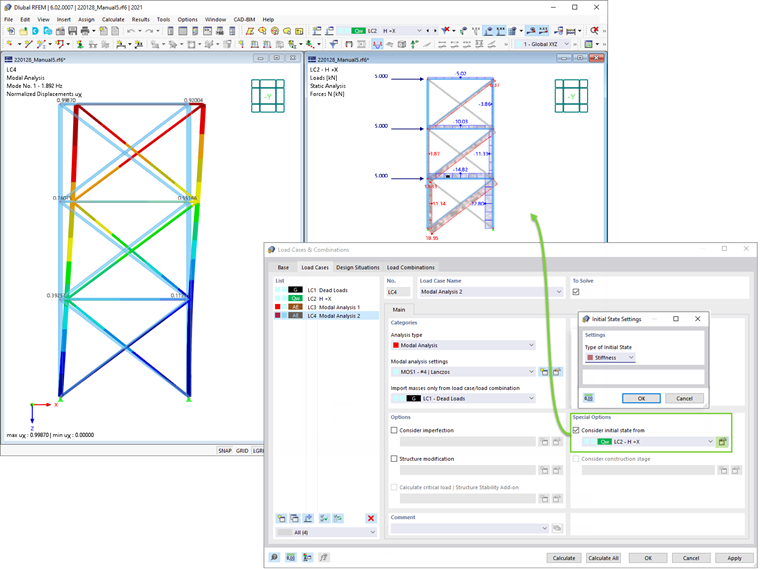
When defining the input data for the modal analysis load case, you can consider a load case whose stiffnesses represent the initial position for the modal analysis. You can do this by using the "Consider initial state from" option shown in Image 6. Hence, if you open the "Initial State Settings" dialog box and define Stiffness as a type of initial state, you can consider the stiffness of the system if tension members fail in the load case from which the initial state is considered. The stiffness from this load case is then considered in the modal analysis and a softer system is obtained.
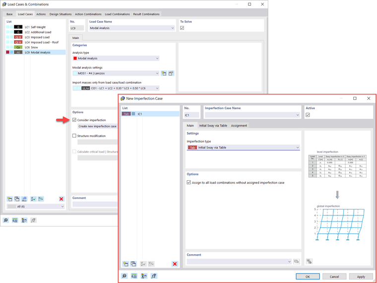
Considering Imperfections
As shown in Image 7, imperfections can also be considered when defining a modal analysis load case. The imperfection types applicable in the modal analysis are notional loads from load case, initial sway via table, static deformation, buckling mode, dynamic mode shape, and group of imperfection cases.
Structure Modifications
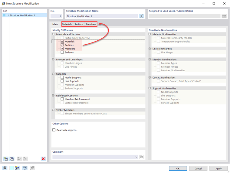
In RFEM 6, you can easily define structural modifications in load cases of the Modal Analysis type. For instance, you can individually adjust the stiffnesses of materials, cross-sections, members, surfaces, hinges, and supports. You can modify stiffnesses for some design add-ons as well. Once you select the objects, their stiffness properties are adapted to the object type, and you can define them in separate tabs, as shown in Image 8.
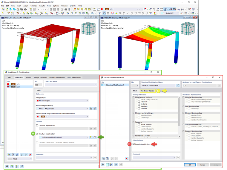
If you are interested in analyzing the failure of an object (for example, a column) in the modal analysis, you can do this in the Structure Modification window by deactivating the objects of interest, as shown in Image 9.
Methods for Determining Number of Mode Shapes
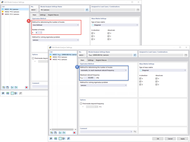
There are two methods available to you for determining the number of mode shapes. The first is to manually define the number of the smallest mode shapes to be calculated. The number of available mode shapes depends on the degrees of freedom (that is, the number of free mass points multiplied by the number of directions in which the masses act), but it is limited to 9,999.
The other option is to set the maximum natural frequency so that mode shapes are automatically determined until the set natural frequency has been reached. Both options are shown in Image 10.
Output of Eigenvalues, Angular Frequencies, Natural Frequencies, Natural Periods, Modal Masses, Effective Modal Masses, Modal Mass Factors, and Participation Factors
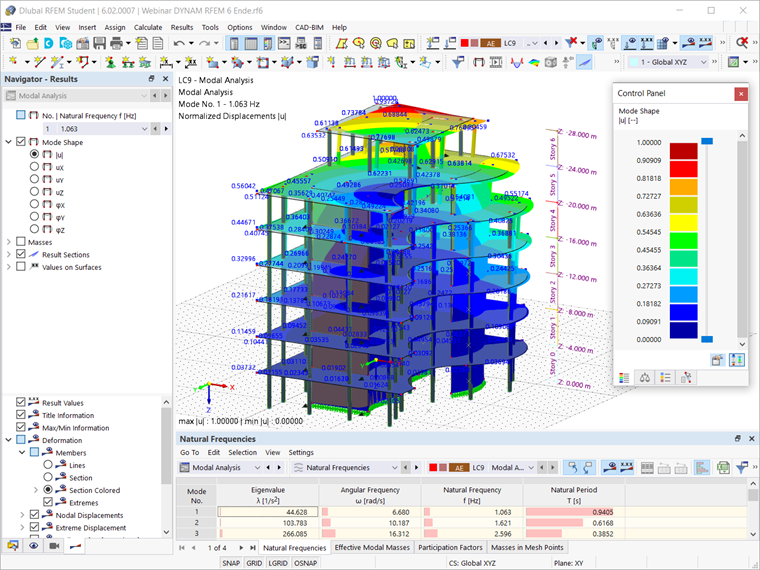
Once the calculation is done, the results of the modal analysis are available both graphically and in tables. In this manner, you can display the Results tables for the Modal Analysis load case(s) and see the eigenvalues, angular frequencies, natural frequencies, and natural periods of the structure. Furthermore, you can display effective modal masses, modal mass factors, and participation factors, as shown in Image 11.
Determination of Masses in Nodes or FE Mesh Points
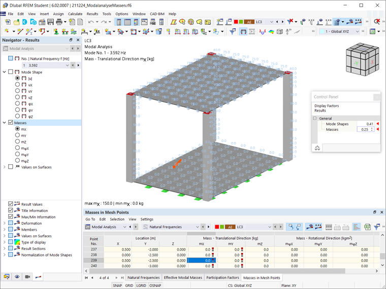
The results of the Modal Analysis in RFEM 6 also include the tabular and graphical output of masses in mesh points. This way, you can check the imported masses that depend on various settings of the modal analysis and can be displayed in the Masses in Mesh Points tab of the Results table.
The table provides an overview of the following results: mass translational directions (mX, mY, mZ), mass rotational directions (mφX, mφY, mφZ), and the sum of the masses. If you are interested in a quick graphical evaluation, you can also display the masses in the mesh points graphically. Both options are shown in Image 12.
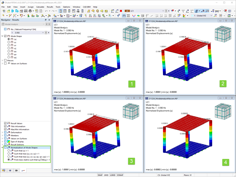
Visualization and Standardization of Mode Shapes
As already mentioned, the results of a Modal Analysis load case are displayed in the program after a successful calculation. Hence, you can immediately see the first mode shape graphically or as an animation. In RFEM 6, you can easily adjust the display of the mode shape standardization.
ou can do this directly in the Results navigator, where you should select one of the three options for the visualization of the mode shapes: scale the value of the mode shape vector uj to 1 (considers only the translation components); select the maximum translational component of the eigenvector and set it to 1; or consider the entire eigenvector (including the rotation components), select the maximum, and set it to 1. This is shown in Image 13.