Thus, the final state of the structure is available upon completion of the construction process; that is, all the construction stages. For some structures, the influence of the construction process (that is, all the individual construction stages) might be significant and it should be considered so that errors in the calculation are avoided. A general overview of the CSA add-on is given in the Knowledge Base article titled “Consideration of Construction Stages in RFEM 6”.
Since different structural parts are associated with individual construction stages, the self-weight of these elements that are active in the specific stage must be taken into account. If the whole structure or its parts is/are subjected to additional loading related to the environmental conditions or the construction method, this must be considered as well.
Hence, in order to define the construction stages, you must include the changes introduced to the model on one hand, and the loading on the other. This article will focus on the former, whereas the latter will be the topic of an upcoming Knowledge Base article.
Practical Example
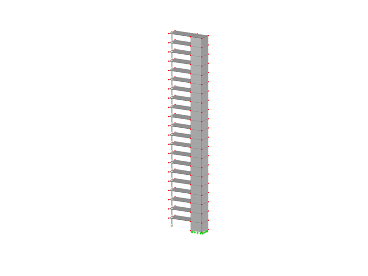
The structure taken as an example in this article has 21 floors and each floor is added in a separate construction stage, thus making 21 consecutive stages overall. The structural elements added in an individual stage are: concrete slabs with a thickness of 20 cm, a shear core made of 40-centimeter-thick walls, and a column with a cross-section of 20x20 cm. The floor height is 3 m. If you perform the FE calculation on this structure as an entire model (that is, without considering the individual construction stages), you will obtain results for the internal forces and deformations as shown in Images 1 and 2, respectively.
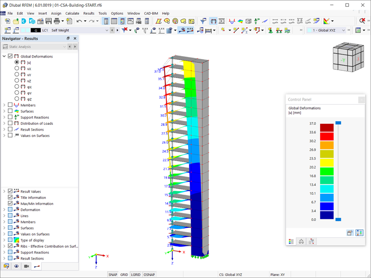
What can be noticed in terms of deformations is that the slabs hang on the inner core. In terms of internal forces, the moments around the support are increasing, whereas the moments in the field decrease from the first to the last floor. This is due to the different stiffness distribution of the structure and the fact that the slabs hang on the core.
In reality, the structure is not built at once; that is, the weight is applied gradually and the results in terms of deformations and internal forces differ from those displayed in the aforementioned images. To take this into account, you should define the individual construction stages that represent the construction process.
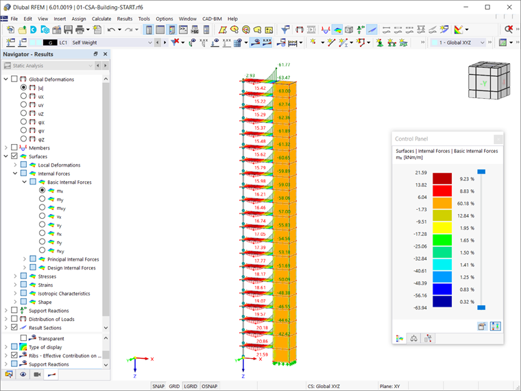
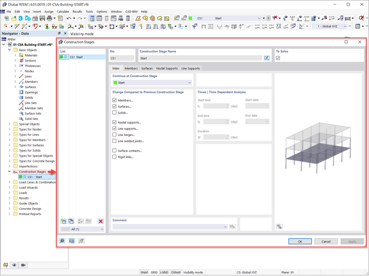
First of all, you should activate the Construction Stages Analysis (CSA) add-on in the Base Data of the model (Image 3). The Construction Stages are then included in the navigator’s data. You can also define stages via the menu bar (Insert → Construction Stages).
To define a new construction stage in RFEM 6, in fact, you should define the changes to be introduced in comparison with the previously defined stage. These changes can be associated with members, surfaces, solids, line supports, nodal supports, line hinges, line welded joints, surface contacts, or rigid links.
Those relevant to the construction stage of interest should be selected in the Main tab of the Construction Stages dialog box. For instance, to define the first stage of the construction process for the structure in this example, you should consider members and surfaces, as well as nodal and line supports (Image 4).
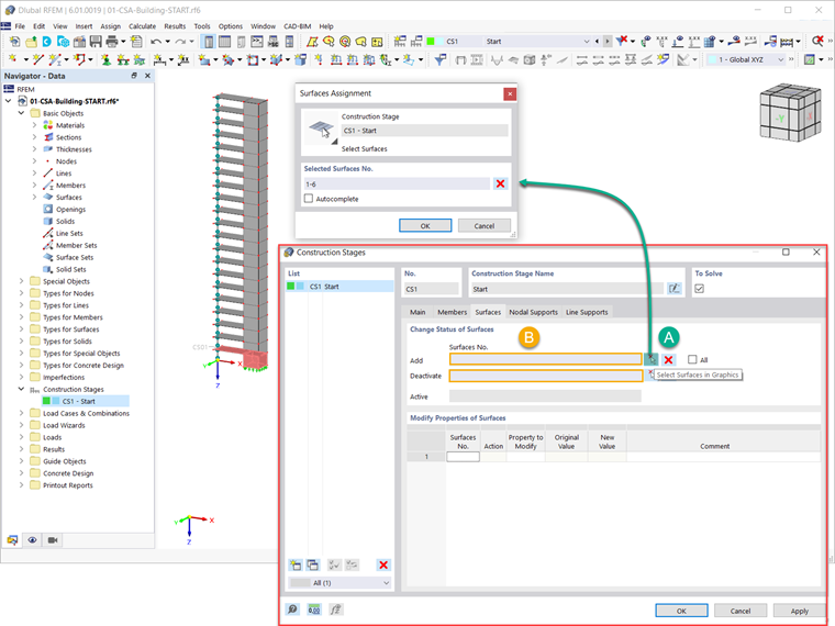
By doing so, you will be able to add or deactivate elements for the specific construction stages. You can do this by selecting the elements of interest in the graphics, or by writing their number in the input field (Image 5).
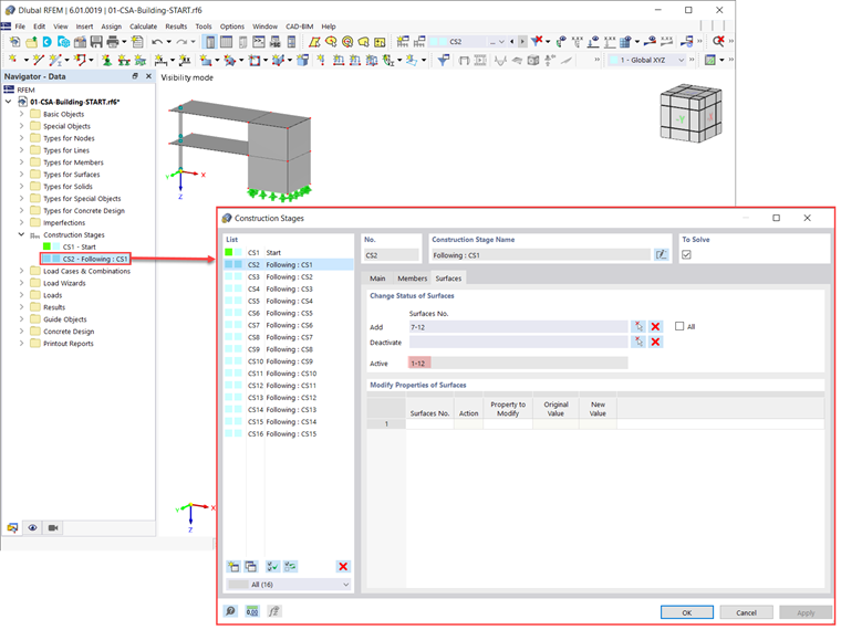
When defining succeeding construction stages (for example, CS2), the selected elements are added to those selected in the preceding stages (that is, CS1). Thus, all of them are active in the current stage, as shown in Image 6.
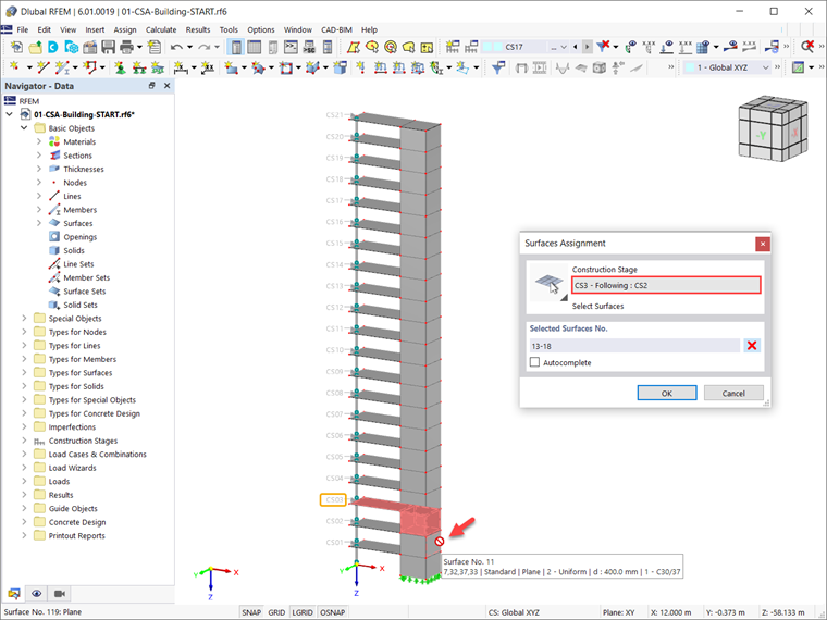
It is important to notice that one element cannot be added in multiple stages. To be more specific, elements you have added in one stage cannot be added in another one. For example, surface No. 11 was added in the second stage (see Image 6), and therefore cannot be selected in the succeeding (third) stage (Image 7).
Once the construction stages are defined on the model side, it is important that you consider the different loading associated with each stage. This will be discussed in an upcoming Knowledge Base article.