Engineering a logistics center in Ukraine with a 39-meter clear span on challenging ground conditions.
Case Study

Engineering 39-Meter Clear-Span Logistics Center on Challenging Ground in Ukraine

Challenge

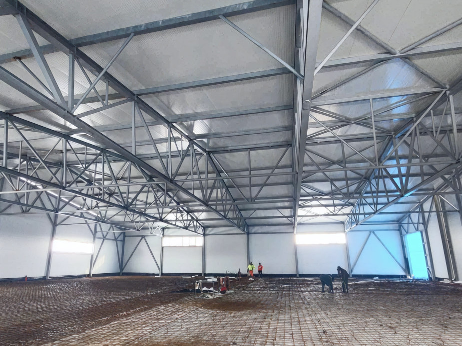
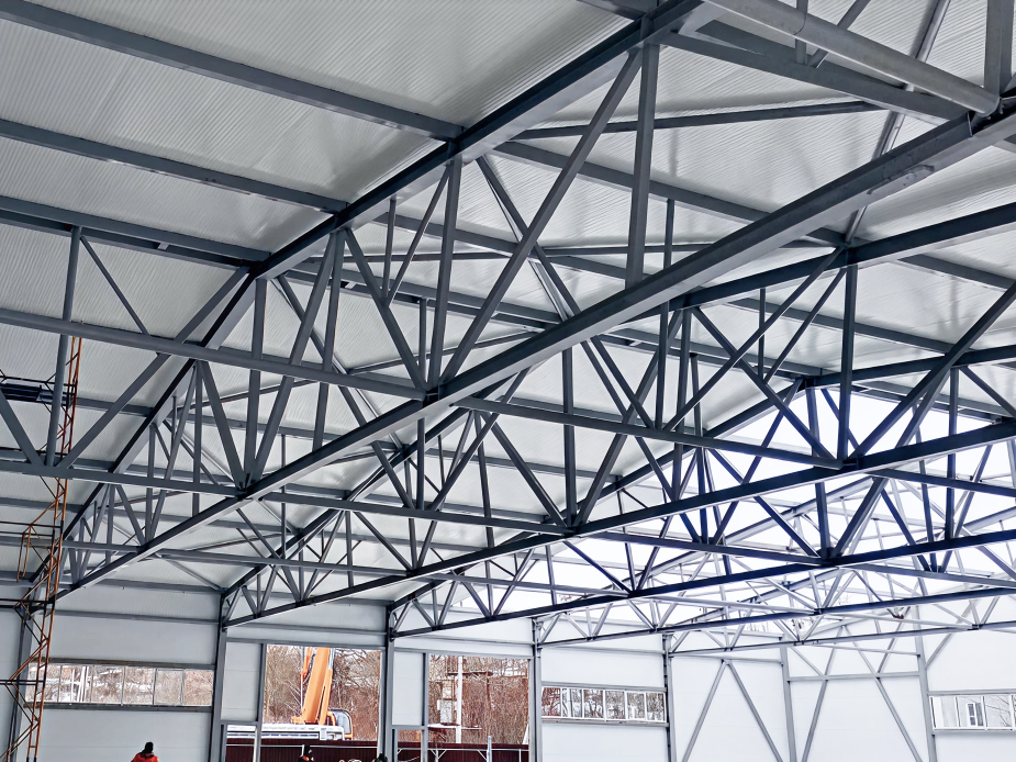
The logistics center in Khmelnytskyi, Ukraine, needed to serve as a column-free warehouse for the clothing brand Stimma — requiring steel trusses with a 39-meter span. The construction site had excellent infrastructure, but geotechnical investigation revealed soil contaminated with rubble and concrete debris, ruling out pile foundations. The question of whether to build at all had to be resolved by precise calculation before anything else could proceed.

Solution

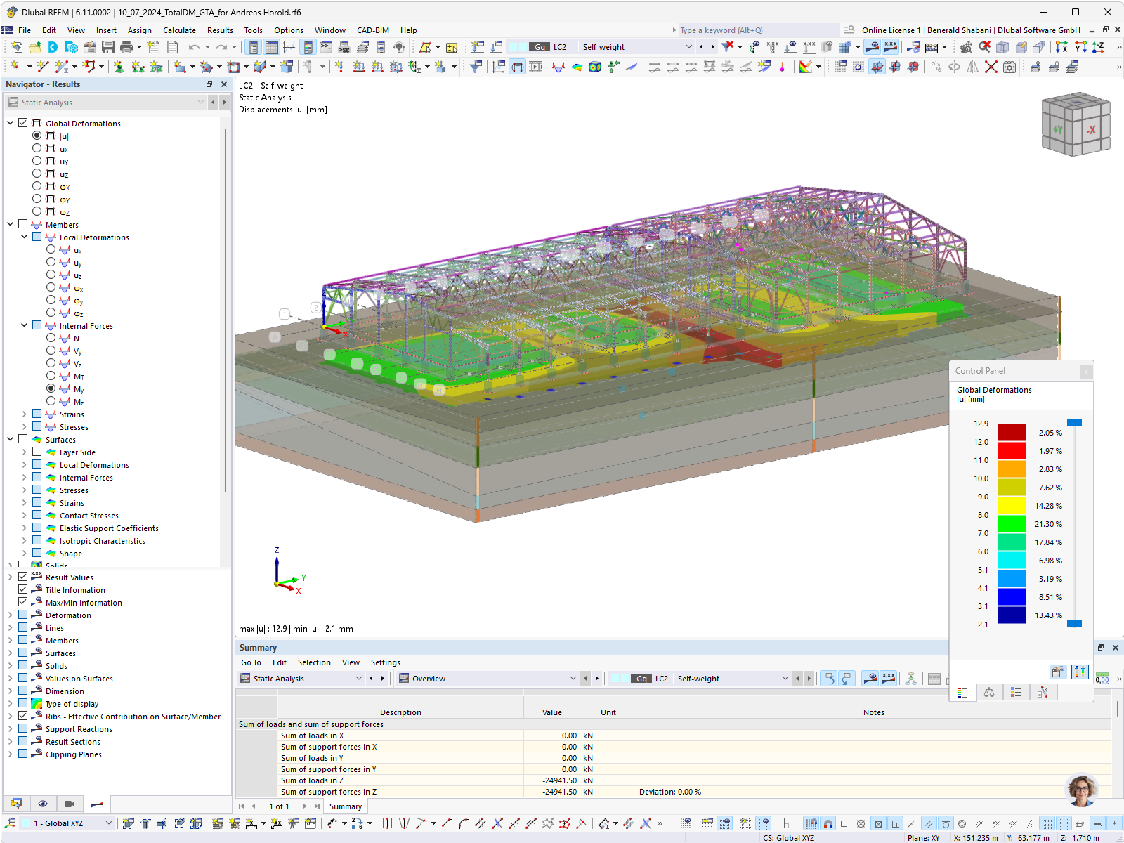
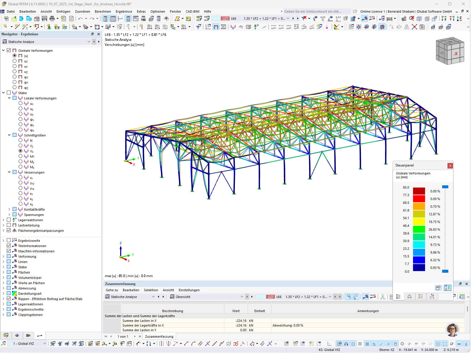
Sergiy Umanskiy used RFEM 6 to analyze the entire structure—foundation, superstructure, and steel joints—within a single integrated model. The Geotechnical Analysis and Construction Stages Analysis add-ons made a shallow foundation feasible and verifiable. The Steel Design and Steel Joints add-ons, used in combination, caught a critical overstress in a vertical brace connection and prompted a timely redesign. Advanced Plastic Design was applied to the I-shaped truss and column cross-sections, delivering smoother, more realistic stress distributions.

Advantages

  • Foundation confidence: Geotechnical calculations made it possible to proceed with a shallow foundation on difficult ground; post-construction measurements confirmed that settlements and crack widths matched the predicted values exactly.
  • Safety through integration: The combined Steel Design and Steel Joints workflow caught overstressed connections before construction, preventing a potentially dangerous structural error.
  • Realistic optimization: Advanced Plastic Design eliminated artificial stress peaks at truss chord joints, producing smoother diagrams and a more efficient use of material.
  • Single workspace efficiency: Geotechnical analysis, superstructure design, and joint verification all operate within one RFEM 6 model, making it straightforward to observe how foundation settlements interact with superstructure deformations simultaneously.
  • Ergonomic interface: Rich visualization—shadows, shading, and color-coded loads—reduces mental effort in daily use and helps identify both weak points and areas of excess material at a glance.

RFEM 6 as Bridge Between Geotechnics and Structural Design

The defining advantage in this project was not simply that geotechnical and structural calculations could be performed—it was that both could be performed in the same model, at the same time. RFEM 6 allowed Sergiy to observe foundation settlements and superstructure deformations simultaneously, so that the interaction between soil behavior and steel response was always visible.

This matters because the two systems are not independent: soil deformation influences how the foundation slab performs, which in turn affects the forces in the columns and trusses above. Carrying out these analyses in separate software, and then trying to reconcile the results by hand, introduces both error and delay. A unified model removes that risk.

After construction, the accuracy of the model was confirmed on site. The measured settlements and crack widths in the foundation remained within the calculated limits—a direct validation of the geotechnical and construction-stage analysis carried out in RFEM 6.

Steel Joints and Safety Net of Integration

The steel structure—columns, 39-meter lattice trusses, purlins, and braces—contains a large number of connections. Sergiy completed the steel member design without issue, but when he moved on to verifying the individual joints using the Steel Joints add-on, he found that several connections produced design ratios above 1.0.

This discovery forced a redesign of the vertical brace lattice before returning to the joint checks. The corrected design passed. The key point is that this problem was identified in the software before it could become a problem on the construction site—a result of the Steel Design and Steel Joints add-ons operating as an integrated pair within one model, rather than as separate, disconnected tools.

Important Features: Joint Stiffness & Cross-Section Optimization

Two advanced capabilities that refined the model's accuracy and made the most of the available cross-section capacity

  • Integrated Joint Stiffness: A further technical benefit came from RFEM 6's ability to feed the calculated initial stiffness of each joint back into the global structural model automatically. Because joint stiffness directly influences deformations and internal forces throughout the structure, this feedback loop between joint-level and system-level analysis improved the precision of the overall results.
  • Advanced Plastic Design: Smoother Stresses, Better Results: For the HE 240 I-sections used in the columns and the top chord of the trusses, the Advanced Plastic Design option was applied. Comparing it directly against linear elastic design, the difference was clear: the elastic approach produced stress peaks at the chord joints, while the plastic approach delivered a smooth, continuous stress diagram along the full length of the chord. The plastic stress values were not only lower and more efficient, they were also more physically representative of how the structure actually behaves.