The form-finding loads are defined using the corresponding object loads. You can define area loads, member loads, and solid loads.
Area loads and member loads have the Form-Finding load type. For solid loads, select the Gas load type.
For objects that are divided, but actually connected in the model, there are also member set loads, surface set loads, and solid set loads. The concept of these loads corresponds to that of the regular loads, so they are not listed again explicitly.
Member Loads
Member loads of the Form-Finding load type can be defined geometrically or as a force.
Member Loads – Geometric Definition Type

The Geometric definition type allows you to define the shape using the following options:
- Length (Lc)
- Unstressed length (Lmfg)
- Sag (S)
- Maximum vertical sag (Smax | Load direction ZL)
- Low-point vertical sag (Slow | Load direction ZL)
All geometric loads can be defined either relatively or absolutely. You can switch between the absolute and relative definitions by clicking the
![]() symbol. In the case of a relative definition, the designation of the load includes the abbreviation rel.
symbol. In the case of a relative definition, the designation of the load includes the abbreviation rel.
The definition of internal forces can be set to tension or compression for all geometric loads. Please note that due to this definition, cables can only absorb tension. For a beam member, by contrast, a shape can be found under tension or compression.

Member Loads – Force Definition Type

The Force definition type allows for shape definition using the following options:
- Average force in member (Tavg)
- Maximum force in member (Tmax)
- Minimum force in member (Tmin)
- Horizontal tension component (Fx)
- Tension at i-end (Ti | Member start)
- Tension at j-end (Tj | Member end)
- Minimum tension at i-end (Tmin, i | Member start)
- Minimum tension at j-end (Tmin, j | Member end)
- Force density (FD)
Surface Loads
Surface loads can have the form-finding definition of force or stress. You can select between the Standard Method and the Projection Method . Furthermore, the form-finding definition of sag is available in the standard method.
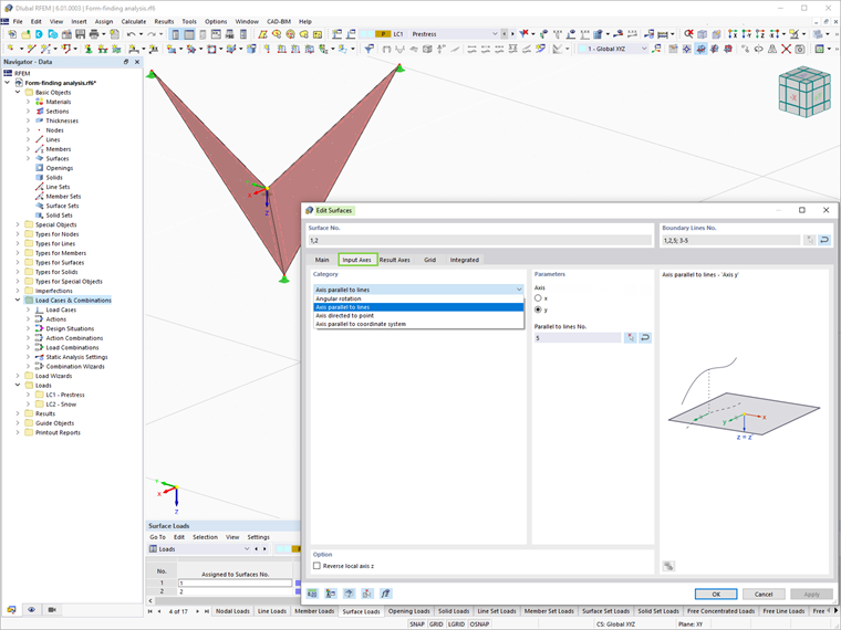
It is important to mention that in order to apply an orthotropic surface prestress, it is necessary to activate the Specific axes option in the Edit Surfaces dialog box and adjust the input parameters of the surfaces accordingly.
Surface Load – Standard Method
The Standard Method describes a vector that can move freely in space up to the target position.

Surface Load – Standard Method
By defining the sag, you can specify the deflection of a membrane and thus model cushions in particular. You specify how far the surface can be deflected and the associated force definition is automatically determined iteratively. You just need to define a ratio of the forces in nx and ny.
The sag can be related to the following imaginary planes:
- Base
- Coordinate system
- Surface
The base refers to the surface itself. The base plane is used. In the case of a curved surface, these are usually the supported edges.
The coordinate system refers to a defined coordinate system. The governing factor here is the Z-axis (or the W-axis for a rotated coordinate system). The sag is measured as a sag from the surface to the axis.
The sag can also be defined with reference to another surface.
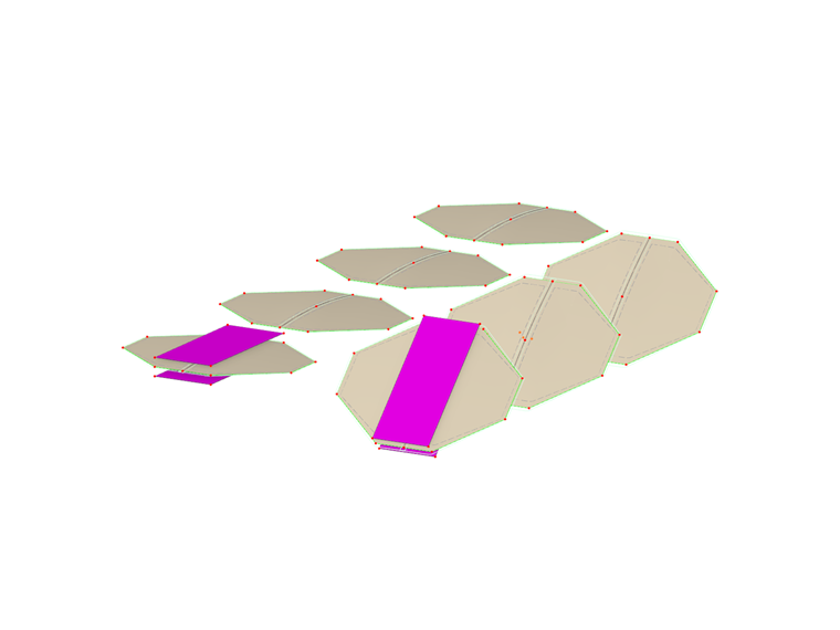
Various models are shown in the following modeling.
Surface Load – Projection Method
The Projection Method can be defined orthogonally or radially in RFEM 6.
For a comparison of the orthogonal and radial projection methods, check the following model file.

The surface loads are defined as follows:
| Number | Load Distribution | Force Definition [kN/m] | Force Definition [kN/m] | Shape | Reason |
|---|---|---|---|---|---|
| 1 | Orthogonal | nx = 2 | ny = 2 | Circular | Same prestress in X and Y |
| 2 | Orthogonal | nx = 2 | ny = 10 | Elliptical | Higher prestress in Y |
| 3 | Orthogonal | nx = 10 | ny = 2 | Elliptical | Higher prestress in X |
| 4 | Radial | nr = 2 | nt = 2 | Circular | Same prestress in r and t |
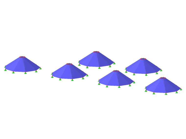
| 5 | Radial | nr = 2 | nt = 10 | Circular, strong cone | Higher prestress in t |
| 6 | Radial | nr = 10 | nt = 2 | Circular, weak cone | Higher prestress in r |
Surface Load – Orthogonal Projection Method
The orthogonal projection method describes a vector that is partially movable in space and fixed on the global XY coordinates.

Surface Load – Radial Projection Method
The radial projection method describes a vector that is partially movable in space and fixed to the defined radial and tangential axes.

For the radial projection method, it is necessary to define the axis. You can easily snap two points in your model using the
![]() button. This is usually a vertical axis at the center of your conical membrane.
button. This is usually a vertical axis at the center of your conical membrane.

Solid Loads
Solid loads of the Gas load type can be defined using various gas behaviors.

Solid Loads – Gas Load Type
The Gas load type allows for the shape definition based on the following gas behavior:
- Resulting overpressure (po)
- Overpressure increment (Δpo)
- Resulting volume (V)
- Volume increment (ΔV)
The terms are defined as follows:
| Abbr. | Description |
|---|---|
| p | Gas pressure |
| pp | Gas initial (atmospheric) pressure |
| po | Gas overpressure |
| Δpo | Gas overpressure increment |
| pa | Current gas pressure (corresponds to pp without the initial state / construction stage) |
| V | Gas solid |
| Va | Current gas volume |
| ΔV | Solid increment |
| T | Gas temperature |
| Tp | Initial gas temperature |