In the next step, new lines and surfaces are to be created by copying objects upwards.
Lower Part
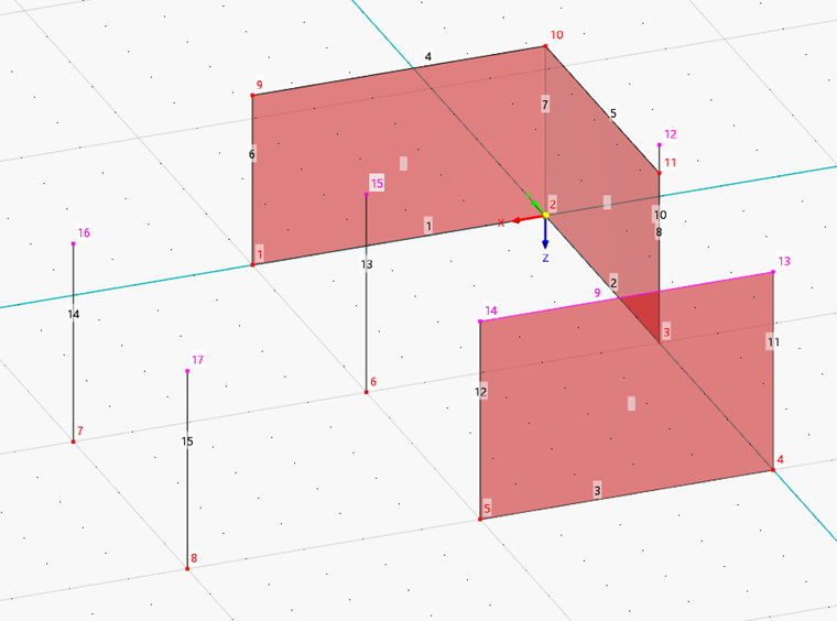
You can use the view cube to rotate the view (see Chapter Model Data). The scroll wheel enables you to zoom in and out.
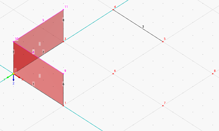
Select lines 1 and 2 by drawing a window over them – from left to right.

The selected objects are characterized by a different color.
Now open the "Move/Copy" function by clicking the
![]() button on the toolbar (alternatively, use the Move/Copy option on the Edit → Manipulation menu).
button on the toolbar (alternatively, use the Move/Copy option on the Edit → Manipulation menu).
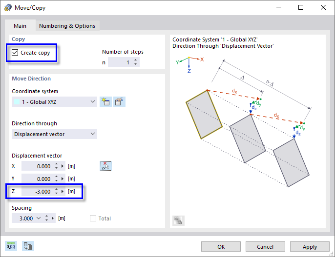
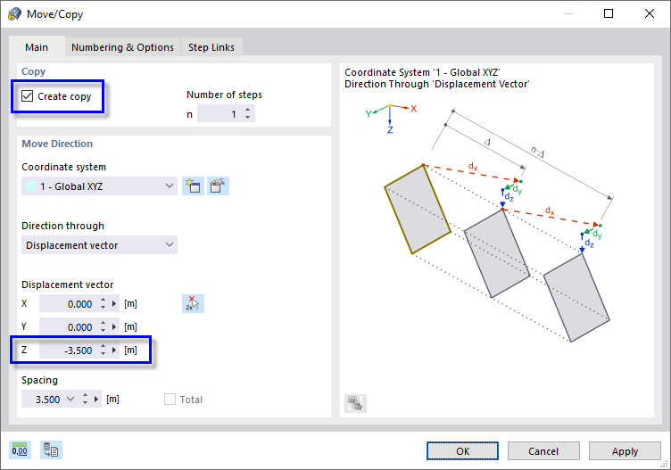
Select the Create copy option in the "Copy" area. Enter the "Displacement vector", which is -3 m in the Z-direction.
Select the Numbering & Options tab.
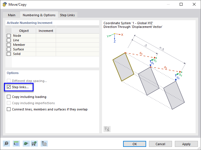
In the "Options" area, select the Step links option. An extra tab is added.
Go to the Step Links tab.
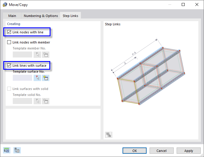
Select the Link nodes with line and Link lines with surface options. Then click OK. New lines and surfaces will be created.
Higher Part
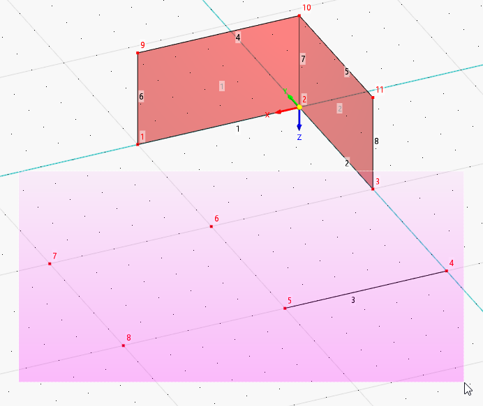
Rotate the view so that you can select line 3 and nodes 3 and 6 through 8 by drawing another window. You can use the view cube to do so.
Open the "Move/Copy" function again by clicking the
![]() button. In the "Move/Copy" dialog box, make sure that the Create copy option is activated in the "Copy" area again. Enter the "Displacement vector", which is -3.5 m this time.
button. In the "Move/Copy" dialog box, make sure that the Create copy option is activated in the "Copy" area again. Enter the "Displacement vector", which is -3.5 m this time.
On the Numbering & Options tab, select the Step links and Connect lines, members and surfaces if they overlap options.

On the "Step Links" tab, make sure that the Link nodes with line and Link lines with surface options are set again (see the "Creating lines and surfaces while copying" image). Then click OK.