


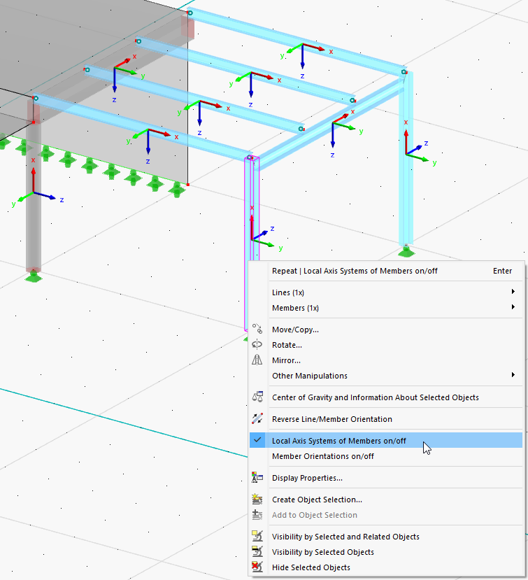
The imperfections refer to the local axes of each column. To display the member axes, right-click one of the members and open its shortcut menu. Select the Local Axis Systems of Members on/off option.
Concrete Column
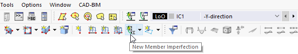
To define the imperfection of the concrete column, click the
![]() button on the toolbar.
button on the toolbar.
In the "New Member Imperfection" dialog box, the imperfection type "Initial Sway" is preset.
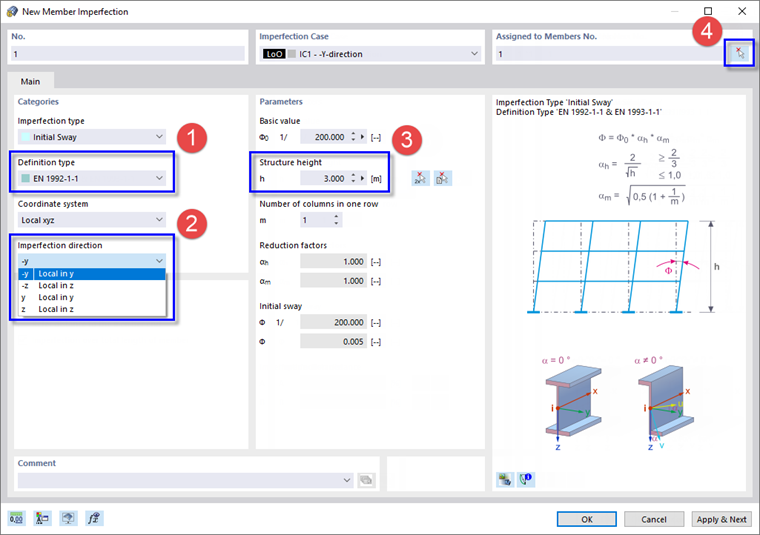
In the "Categories" area, select EN 1992-1-1 from the "Definition type" list (1) so that the parameters according to Eurocode 2 are to be applied.
Move the dialog box so that you can see the axes of the concrete column. Its local y-axis points in the global Y-direction. To apply the sway in the opposite direction, select -y from the list in the "Imperfection direction" area (2).
In the "Parameters" area, enter the column height, which is 3 m (3). Next click the
![]() button in the "Assigned to Members" area (4) and select the concrete column in the graphics. Click OK to return to the dialog box.
button in the "Assigned to Members" area (4) and select the concrete column in the graphics. Click OK to return to the dialog box.
Continue defining imperfections by clicking Apply & Next.
Steel Columns
Sway
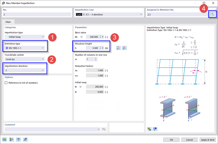
Select EN 1993-1-1 from the "Definition type" list (1) to apply the parameters according to Eurocode 3 for the steel columns. Due to the rotation of the columns, their local z-axes point in the negative Y-direction. Select z from the "Imperfection direction" list (2).
Enter the column height, which is 3.5 m (3). Then click the
![]() button again (4) to select the two steel columns one by one in the graphics. When you return to the dialog box, their numbers are shown in the "Assigned to Members" area.
button again (4) to select the two steel columns one by one in the graphics. When you return to the dialog box, their numbers are shown in the "Assigned to Members" area.
Click Apply & Next again.
Bow
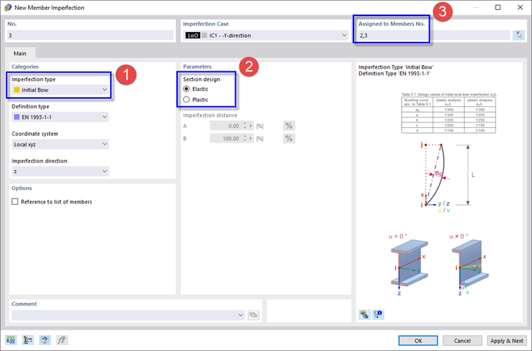
In the "Categories" area, select the Initial Bow imperfection type (1). Make sure that EN 1993-1-1 is set. As no plastic analysis is to be carried out, set the Elastic option in the "Parameters" area (2). Then enter the numbers of the steel column members nos. 2,3 manually (3), unless you want to select them graphically again.
Bow imperfections are only relevant to the steel columns, not to the concrete column. Therefore, close the dialog box by clicking OK.
If the imperfections are not displayed on the model, use the
![]() button to switch them on.
button to switch them on.
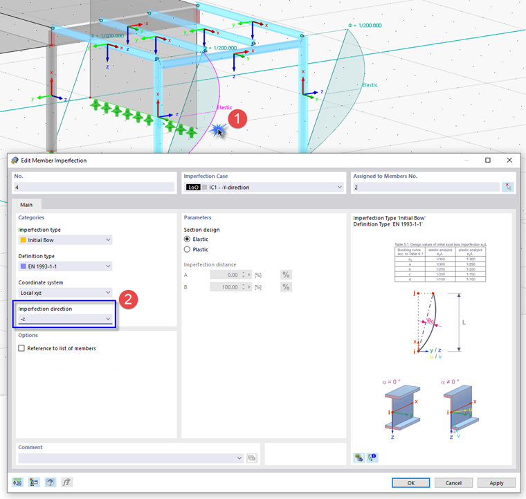
The graphic shows that the bow imperfections do not yet fully reflect the buckling shape of a frame. Double-click the bow imperfection of the interior column (member no. 2) to adjust it (1). In the "Edit Member Imperfection" dialog box, invert the "Imperfection direction" by selecting -z from the list (2). Then click OK.
To hide the member axes again, right-click one of the members and deselect the Local Axis Systems of Members option in its shortcut menu (see the Displaying Local Axes of Members image).
Wireframe model
The display of the model can be modified for a better of view of the imperfections: Click the
![]() list button on the toolbar to open the display options. Select the Wireframe Model.
list button on the toolbar to open the display options. Select the Wireframe Model.
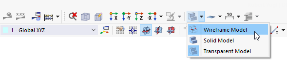
Now the imperfections are no longer overlapped by the sections.
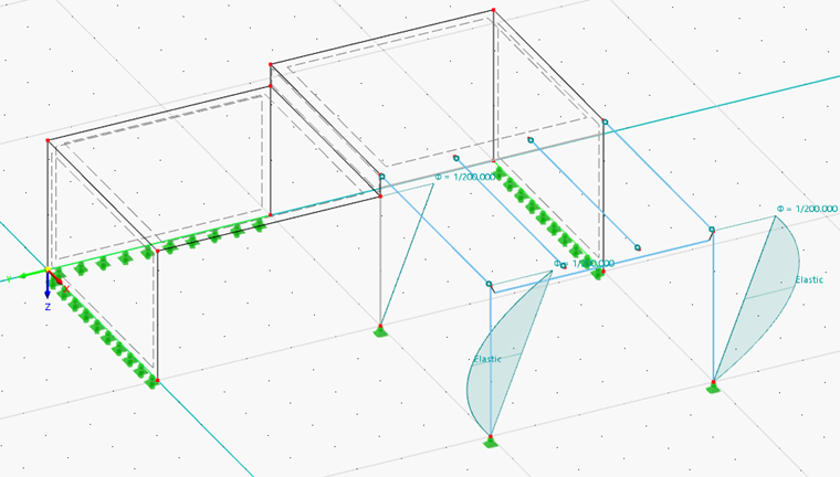
Restore the Transparent Model view by selecting the corresponding option in the list button (see the Selecting Display of 'Wireframe Model' image).