


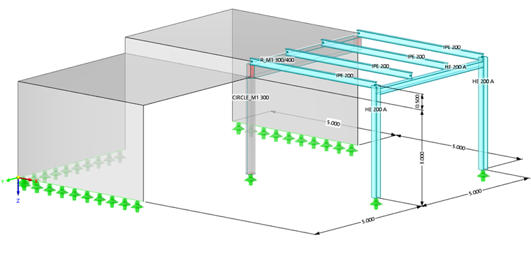
The model represents a concrete structure with a steel platform attached. There are two slabs with a vertical offset between them. The slabs are supported by three concrete walls and one column. One surface has a T-beam integrated at a free edge. All surfaces are rigidly connected.
The adjacent platform is supported by a frame construction at its remote end. Since the platform girders are pin-connected to the slab and frame, they do not transfer any bending moments.
Materials, Thicknesses, and Sections
For the materials, concrete C30/37 and steel S 235 are used for the structural model.
The thickness of the floors and walls is 20 cm each. The concrete column in the centre of the model consists of a circular section 30 cm in diameter. For the downstand beam, a rectangular section 30 cm wide by 50 cm deep is used. The steel frame consists of HE-A 200 sections, whereas the platform girders are made of IPE 200 sections.
Loads
The loads are applied through four load cases (LC).
LC1 includes the self-weight of the model and the weight of the floor on the slabs which is 0.75 kN/m².
In LC2 through LC4, the live loads are defined. Those are category A loads of 1.50 kN/m² each and are applied separately to the two slabs and the platform.
Imperfections
For individual members, the effects of imperfections should be considered according to Eurocode 3, for example. Imperfections are accounted for as separate categories, not as load cases (like in previous program versions).
For all columns, the initial sway imperfections are ϕ0 = 1/200. They are individually applied in the opposite Y-direction so that they reflect the lowest mode shapes of the model. Additionally, initial local bow imperfections e0/L = 1/200 are considered for the steel columns in the same direction (buckling curve c for member z-axis). Bow imperfections are not relevant to the concrete column according to Eurocode 2.