Generating the Mesh
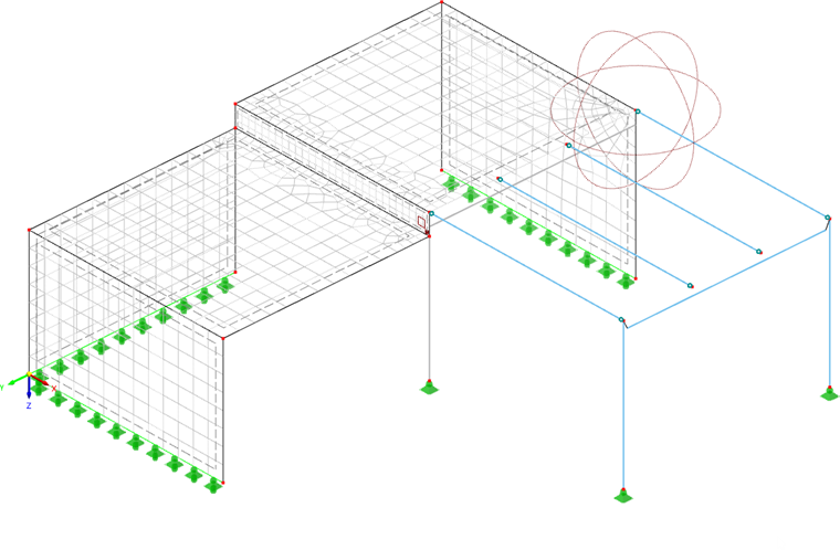
To create the FE mesh with the default settings, select the Calculate menu and click Generate Mesh. When it has been generated, the mesh is displayed on the surfaces of the model (if it is not shown, go to the Calculate menu again and select Display Mesh).
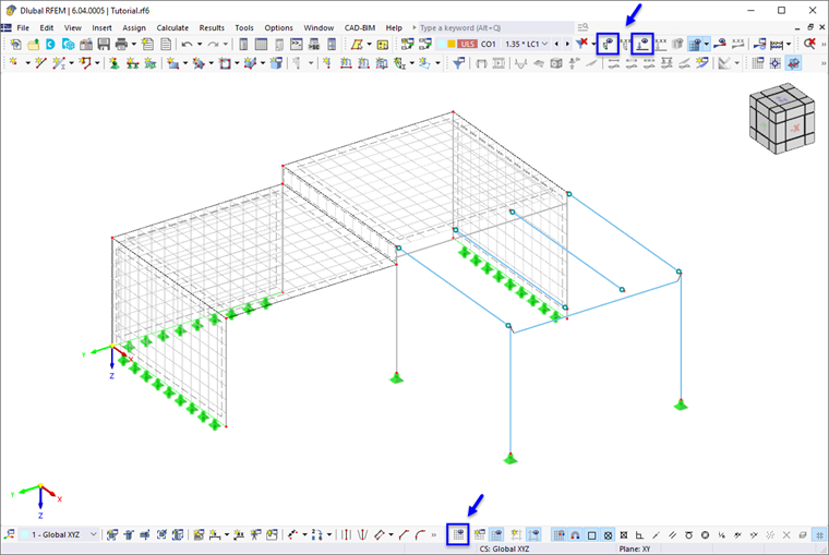
For a better view of the mesh, you can use the
![]() button on the status bar to switch the work plane grid off. Use the
button on the status bar to switch the work plane grid off. Use the
![]() and
and
![]() buttons on the toolbar to hide the imperfections and loads.
buttons on the toolbar to hide the imperfections and loads.
Adjusting the Mesh Size
You can check the settings that are applied to the mesh by default. Select the Calculate menu again and click Mesh Settings.
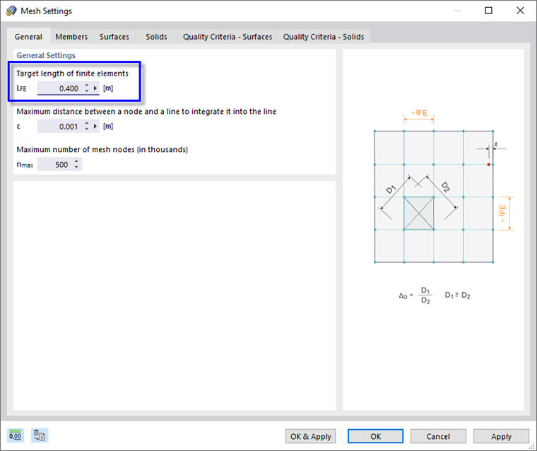
The "General Settings" area of the first tab controls the target length of finite elements – the mesh size which is applied globally to all objects of the model. Enter the value of 0.40 m for a more refined mesh.
Click OK & Apply to create the mesh with the new settings.
Applying Mesh Refinements
Surface Mesh Refinement
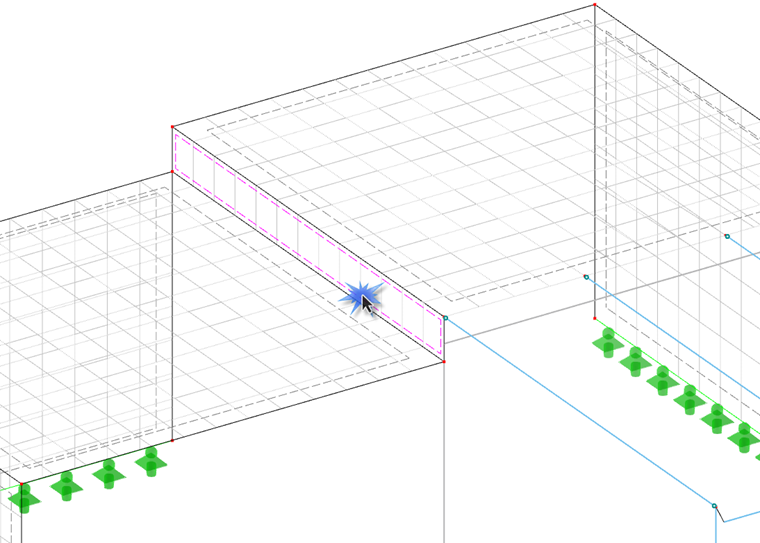
With the height of the connecting surface (no. 6) of 50 cm, only one row of finite elements is created between its upper and lower boundary lines. This is not sufficient for an adequate analysis.
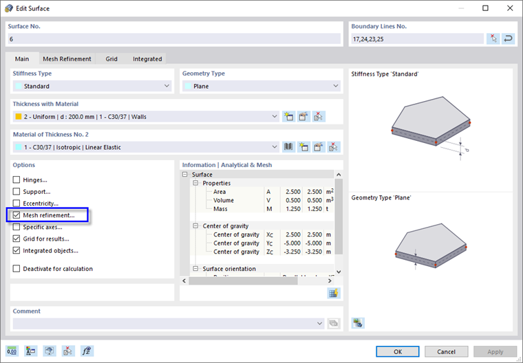
To create three rows of elements, define a surface mesh refinement: Double-click surface no. 6 by the dashed lines that symbolize the surfaces in the wireframe model. Zoom in, if necessary.
In the "Edit Surface" dialog box, select the Mesh refinement check box in the "Options" area.
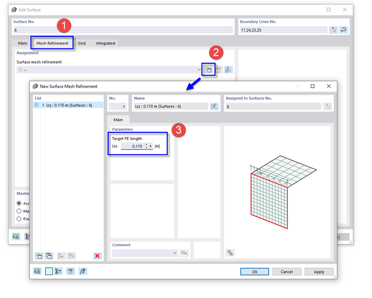
Then click the Mesh Refinement tab (1).
In the "Assignment" area, click the
![]() button to create a new mesh refinement (2). The "New Surface Mesh Refinement" dialog box opens. Enter the target length of 0.17 m in the "Parameters" area (3) so that three elements are created over the height of 50 cm.
button to create a new mesh refinement (2). The "New Surface Mesh Refinement" dialog box opens. Enter the target length of 0.17 m in the "Parameters" area (3) so that three elements are created over the height of 50 cm.
Click OK twice to close the two dialog boxes. A rectangular symbol is shown in one corner of the surface. It symbolizes the mesh refinement.
Nodal Mesh Refinement
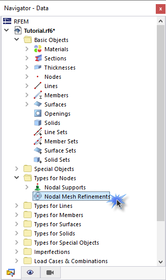
Areas of mesh refinements can also be defined around specific nodes. To apply a different method, open the Types for Nodes folder in the navigator. Then double-click Nodal Mesh Refinements.
In the "New Nodal Mesh Refinement" dialog box, the circular refinement type is preset. Enter the radius of 1.5 m and the inner target length of 0.2 m in the "Parameters" area (1).
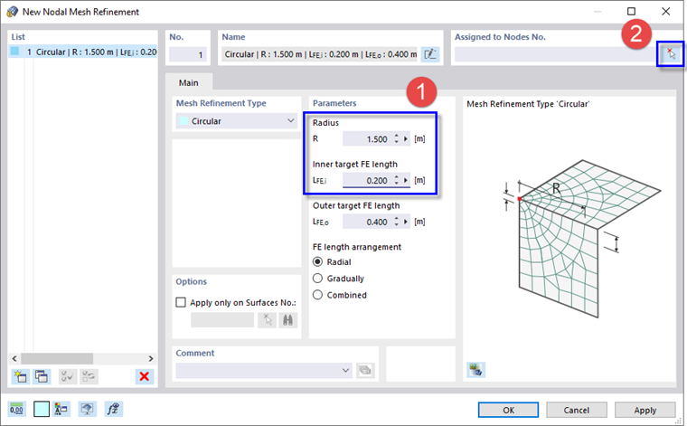
To assign this new type of refinement graphically to a node, click the
![]() button (2). Select the corner node no. 14 at the connection between the wall and the platform.
button (2). Select the corner node no. 14 at the connection between the wall and the platform.
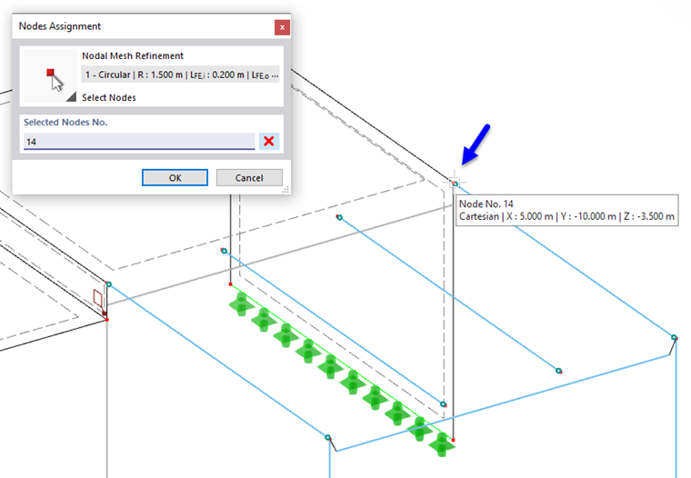
Close the "Nodes Assignment" dialog box by clicking OK.
Click OK again to close the "New Nodal Mesh Refinement" dialog box. A spherical symbol is shown around the node which represents its mesh refinement area (if it is not displayed, activate the "Nodal Mesh Refinements" option in the "Display" navigator).
Finally, create the mesh again by clicking Generate Mesh on the Calculate menu.