
Continuous beam with four spans is loaded by axial and bending forces (replacing imperfections). All supports are fork - warping is free. Determine displacements uy and uz, moments My, Mz, Mω and MTpri and rotation φx. The verification example is based on the example introduced by Gensichen and Lumpe.
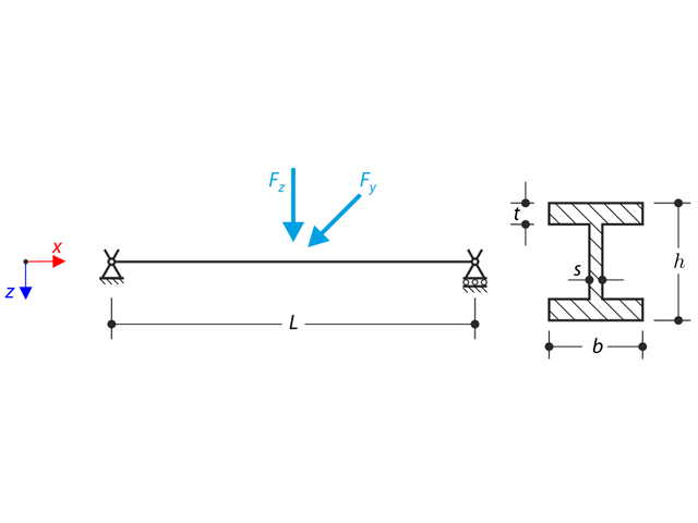
The axial rotation of the I-profile is restricted on the both ends by means of the fork supports (warping is not restricted). The structure is loaded by two transverse forces in its middle. The self-weight is neglected in this example. Determine the maximum deflections of the structure uy,max and uz,max, maximum rotation φx,max, maximum bending moments My,max and Mz,max and maximum torsional moments MT,max, MTpri,max, MTsec,max and Mω,max. The verification example is based on the example introduced by Gensichen and Lumpe.
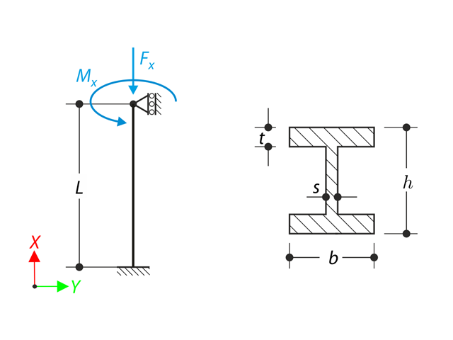
A member with the given boundary conditions is loaded by torsional moment and axial force. Neglecting its self-weight, determine the beam's maximum torsional deformation as well as its inner torsional moment, defined as the sum of a primary torsional moment and torsional moment caused by the normal force. Provide a comparison of those values while assuming or neglecting the influence of the normal force. The verification example is based on the example introduced by Gensichen and Lumpe.
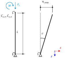
A cantilever is loaded by a moment at its free end. Using the geometrically linear analysis and large deformation analysis, and neglecting the beam's self-weight, determine the maximum deflections at the free end. The verification example is based on the example introduced by Gensichen and Lumpe.
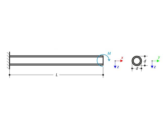
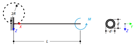
A thin-walled cantilever of a QRO-profile is fully fixed on the left end and warping is free. The cantilever is subjected to torque. Small deformations are considered, and the self-weight is neglected. Determine the maximum rotation, primary moment, secondary moment, and warping moment. The verification example is based on the example introduced by Gensichen and Lumpe.
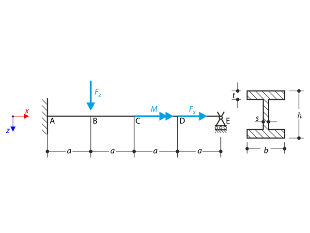
A beam is fully fixed (warping is restricted) on the left end and supported by a fork support (free warping) on the right end. The beam is subjected to a torque, longitudinal force, and transverse force. Determine the behavior of the primary torsional moment, secondary torsional moment and warping moment. The verification example is based on the example introduced by Gensichen and Lumpe (see reference).
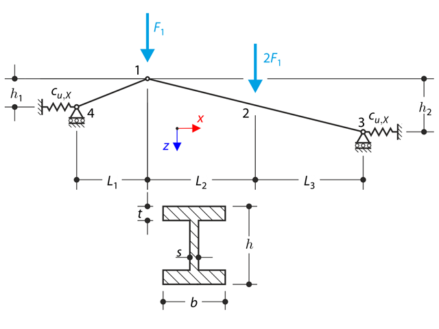
A structure made of I-profile trusses is supported on the both ends by the spring sliding supports and loaded by the transversal forces. The self-we ight is neglected in this example . Determine the deflection of the structure, the bending moment, the normal force in given test points and horizontal deflection of the spring support.
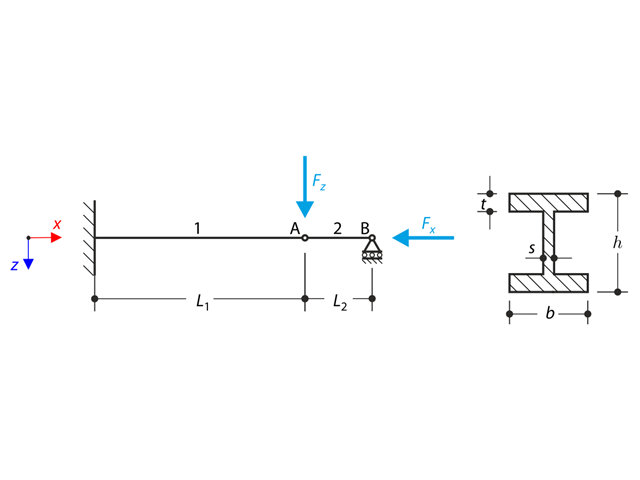
A structure made of I-profile is fully fixed on the left end and embedded into the sliding support on the right end. The structure consists of two segments. The self-weight is neglected in this example. Determine the maximum deflection of the structure uz,max, the bending moment My on the fixed end, the rotation &svarphi;2,y of the segment 2 and the reaction force RBz by means of the geometrically linear analysis and the second-order analysis. The verification example is based on the example introduced by Gensichen and Lumpe.
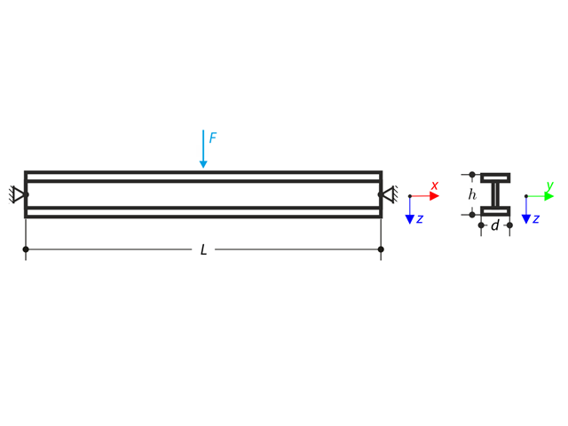
Beam pinned at the both ends is loaded by means the transversal force at the middle. Neglecting its self-weight and shear stiffness, determine the maximum deflection, normal force and moment at the mid-span assuming the second and the third order theory. The verification example is based on the example introduced by Gensichen and Lumpe (see the reference).

The model is based on the example 4 of [1]: Point-supported slab.
The flat slab of an office building with crack-sensitive lightweight walls is to be designed. Inner, border and corner panels are to be investigated. The columns and the flat slab are monolithically joined. The edge and corner columns are placed flush with the edge of the slab. The axes of the columns form a square grid. It is a rigid system (building stiffened with shear walls).
The office building has 5 floors with a floor height of 3.000 m. The environmental conditions to be assumed are defined as "closed interior spaces". There are predominantly static actions.
The focus of this example is to determine the slab moments and the required reinforcement above the columns under full load.
Determine the required strengths and effective length factors for the ASTM A992 material columns in the moment frame shown in Figure 1 for the maximum gravity load combination, using LRFD and ASD.

Using AISC Manual tables, determine the available compressive and flexural strengths and whether the ASTM A992 W14x99 beam has sufficient available strength to support the axial forces and moments shown in Figure 1, obtained from a second-order analysis that includes P-𝛿 effects.
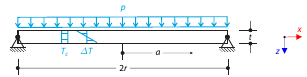
Determine the maximum deflection and maximum radial moment of a simply supported circular plate subjected to uniform pressure, uniform temperature, and differential temperature.
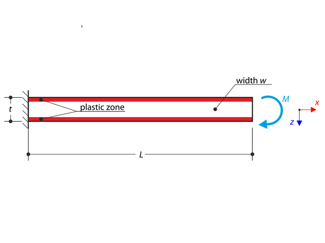
A cantilever is fully fixed on the left end and loaded by a bending moment on the right end. The material has different plastic strengths under tension and compression.
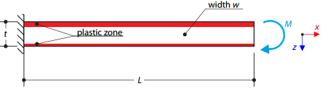
A cantilever is fully fixed on the left end and loaded by a bending moment. Plastic material is considered for the calculation.
A cantilever is fully fixed on the left end and subjected to a bending moment considering plasticity.
Determine the required strengths and effective length factors for the ASTM A992 material columns in the moment frame shown in Figure 1 for the maximum gravity load combination, using LRFD and ASD.
Using AISC Manual tables, determine the available compressive and flexural strengths and whether the ASTM A992 W14x99 beam has sufficient available strength to support the axial forces and moments shown in Figure 1, obtained from a second-order analysis that includes P-𝛿 effects.

A column is composed of a concrete section (rectangle 100/200) and a steel section (profile I 200). It is subjected to pressure force. Determine the critical load and corresponding load factor. The theoretical solution is based on the buckling of a simple beam. In this case, two regions have to be taken into account due to different moments of inertia and material properties.
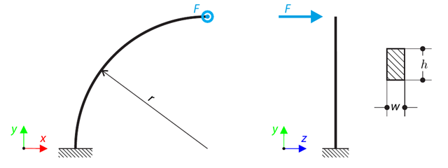
A quarter-circle beam with a rectangular cross-section is loaded by means of an out-of-plane force. This force causes a bending moment, torsional moment, and transverse force. While neglecting self-weight, determine the total deflection of the curved beam.
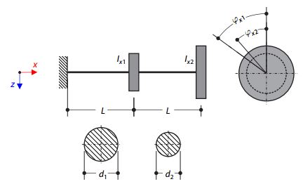
A double‑mass system consists of two shafts and two masses represented by the corresponding moments of inertia, concentrated in a given distance as nodal masses. The left shaft is fixed, and the right mass is free. Neglecting the self‑weight of the shafts, determine the torsional natural frequencies of the system.
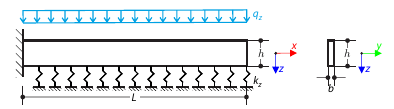
A cantilever from a rectangular cross-section is lying on an elastic Pasternak foundation and loaded by distributed loading. The image shows the calculation of the maximum deflection and maximum bending moment.
A structure made of an I-profile is fully fixed on the left end and embedded into the sliding support on the right end. The structure consists of two segments. The self-weight is neglected in this example. Determine the maximum deflection of the structure, the bending moment on the fixed end, the rotation of segment 2, and the reaction force at point B by means of the geometrically linear analysis and the second-order analysis. The verification example is based on the example introduced by Gensichen and Lumpe.
A thin-walled cantilever of a QRO-profile is fully fixed on the left end and warping is enabled. The cantilever is subjected to torque. Small deformations are considered, and the self-weight is neglected. Determine the maximum rotation, primary moment, secondary moment, and warping moment. The verification example is based on the example introduced by Gensichen and Lumpe.
A cantilever is loaded by a moment at its free end. Using the geometrically linear analysis and large deformation analysis, and neglecting the beam's self-weight, determine the maximum deflections at the free end. The verification example is based on the example introduced by Gensichen and Lumpe.
A member with the given boundary conditions is loaded by torsional moment and axial force. Neglecting its self-weight, determine the beam's maximum torsional deformation as well as its inner torsional moment, defined as the sum of a primary torsional moment and torsional moment caused by the normal force. Provide a comparison of those values while assuming or neglecting the influence of the normal force. The verification example is based on the example introduced by Gensichen and Lumpe.
Consider a rigid scaffolding tube, fixed at the bottom using the Scaffolding Nodal Support and loaded by both a moment and a force. Calculate the maximum deflection with consideration of initial slippage.
Consider a rigid scaffolding tube, fixed at the bottom using the Scaffolding Nodal Support and loaded by both a moment and a force. Calculate the maximum radial deflection by exceeding the capacity of the scaffolding support.
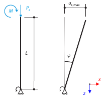
Determine the bending moment which, acting at the free end of the cantilever, will bend the member into a circular shape. Neglecting the beam's self-weight, assuming the large deformation analysis, and loading the cantilever with the moment, determine its maximum deflections.
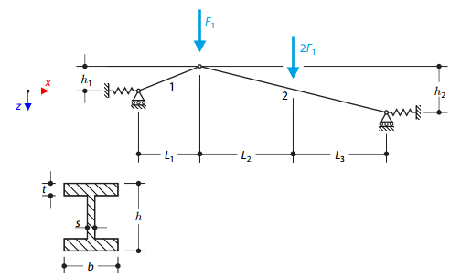
A structure made of I-profile trusses is supported on both ends by spring sliding supports and loaded by transversal forces. The self-weight is neglected in this example. Determine the deflection of the structure, the bending moment, the normal force in the given test points, and the horizontal deflection of the spring supports.