


Description
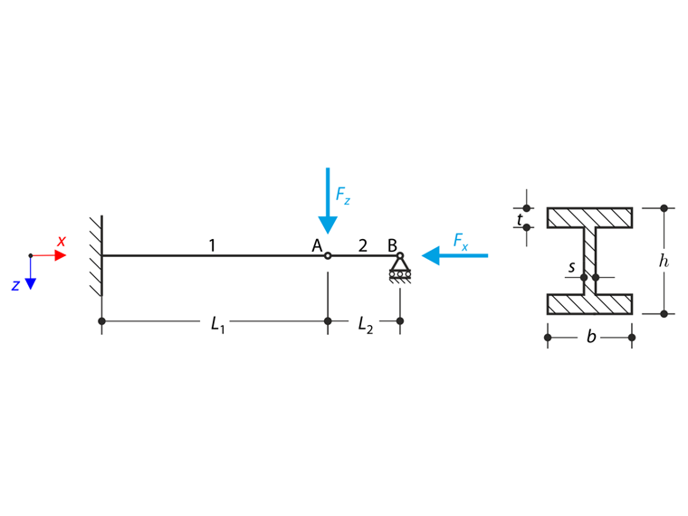
A structure made of I-profiles is fully fixed on the left end and embedded into the sliding support on the right end. The structure consists of two segments. The self-weight is neglected in this example. Determine the maximum deflection of the structure uz,max, the bending moment My on the fixed end, the rotation &svarphi;2,y of segment 2 and the reaction force RBz by means of the geometrically linear analysis and the second-order analysis. The verification example is based on the example introduced by Gensichen and Lumpe (see the reference).
| Material | Steel | Modulus of Elasticity | E | 210000.000 | MPa |
| Poisson's Ratio | ν | 0.300 | - | ||
| Geometry | Structure | Segment Length 1 | L1 | 6.000 | m |
| Segment Length 2 | L2 | 1.200 | m | ||
| Cross-section | Height | h | 400.000 | mm | |
| Width | b | 180.000 | mm | ||
| Web Thickness | s | 10.000 | mm | ||
| Flange Thickness | t | 14.000 | mm | ||
| Load | Axial Force | Fx | 100.000 | kN | |
| Transverse Force | Fz | 0.500 | kN | ||
Analytical Solution
Geometrically Linear Analysis
Geometrically linear analysis is carried out first. In this case, the axial force Fx is not taken into account. The problem can then be solved as well as a cantilever of the length L1 loaded only by the transverse force Fz. The maximum deflection uz,max can be calculated using Mohr's integral and results into expression:
|
F<sub>y</sub> |
Quadratic moment of the cross-section with respect to the y-axis |
The bending moment on the fixed end can be calculated according to the following formula:
The rotation of segment 2 φ2,y is calculated from the geometric condition as follows:
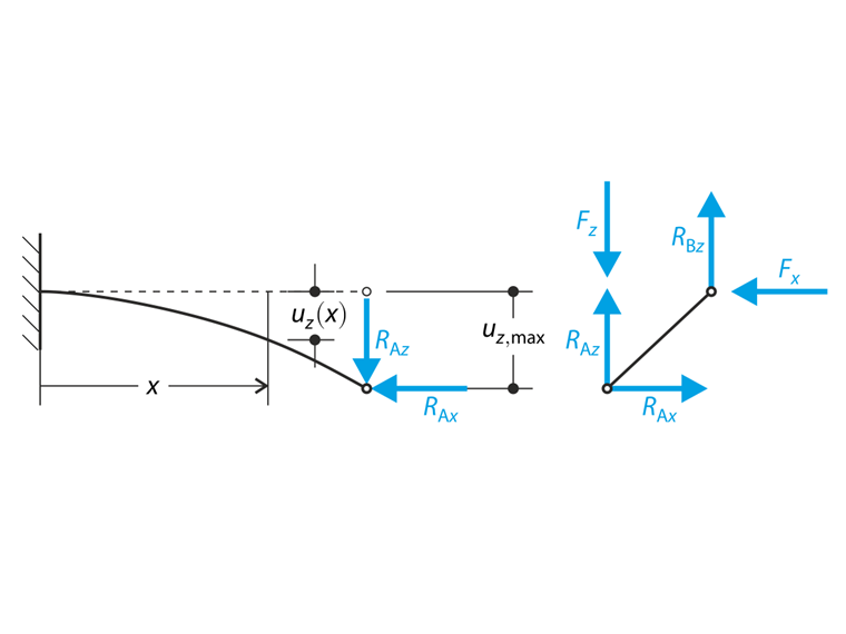
The reaction force in sliding joint RBz considering the zero effect of the axial force Fx can be obtained from the free body diagram shown in the following sketch.
Second-Order Analysis
Because of the non-negligible effect of the axial force Fx, the second-order analysis should be considered. Thus the axial force Fx is taken into account and produces another contribution to the bending moment. The problem can be described by the free body diagram of the segments according to the sketch. The unknown reaction forces can be obtained from the equilibrium equations and then the bending moment formula can be written.
The solution can be found by the Euler-Bernoulli differential equation.
Considering boundary conditions, the solution on the differential equation can be found and the maximum deflection of the structure calculated.
The bending moment on the fixed end can be calculated according to the following formula:
The rotation of segment 2 φ2,y is calculated from the geometric condition as follows:
The reaction force in sliding joint RBz results:
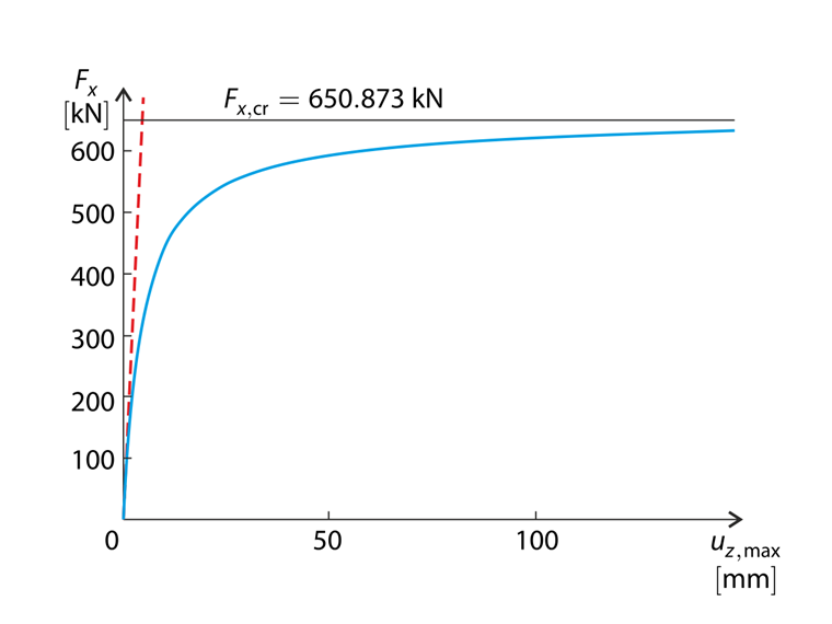
It is obvious that the influence of the axial force Fx is considerable. The total deflection of the structure under the prescribed loading in the case of the second-order analysis is approximately 18% greater than in the case of the geometrically linear analysis. The comparison of the geometrically linear analysis and the second-order analysis is shown in the graph, considering the ratio of the loading forces Fz = Fx/200. It is obvious that the difference between these analyses is more considerable when the loading is greater. The second-order analysis solution approaches the horizontal asymptote. The numerical solution gives the value of the horizontal asymptote Fx,cr = 650.873 kN.
RFEM and RSTAB Settings
- Modeled in RFEM 5.05, RSTAB 8.05 and RFEM 6.01, RSTAB 9.01
- The number of elements is 2 (one element per member)
- The number of increments is 5
- Isotropic linear elastic material model is used
- The structure is modeled using members
- Shear stiffness of the members is neglected
Results
| Geometrically Linear Analysis | Analytical Solution | RFEM 6 | Ratio | RSTAB 9 | Ratio |
| uz,max [mm] | 0.743 | 0.743 | 1.000 | 0.743 | 1.000 |
| My(0) [kNm] | 3.000 | 3.000 | 1.000 | 3.000 | 1.000 |
| φ2,y [mrad] | 0.619 | 0.619 | 1.000 | 0.619 | 1.000 |
| RBz [kN] | 0.000 | 0.000 | - | 0.000 | - |
| Geometrically Linear Analysis | Analytical Solution | RFEM 5 | Ratio | RSTAB 8 | Ratio |
| uz,max [mm] | 0.743 | 0.743 | 1.000 | 0.743 | 1.000 |
| My(0) [kNm] | 3.000 | 3.000 | 1.000 | 3.000 | 1.000 |
| φ2,y [mrad] | 0.619 | 0.619 | 1.000 | 0.619 | 1.000 |
| RBz [kN] | 0.000 | 0.000 | - | 0.000 | - |
| Second-Order Analysis | Analytical Solution | RFEM 6 | Ratio | RSTAB 9 | Ratio |
| uz,max [mm] | 0.878 | 0.878 | 1.000 | 0.878 | 1.000 |
| My(0) [kNm] | 3.527 | 3.527 | 1.000 | 3.527 | 1.000 |
| φ2,y [mrad] | 0.732 | 0.732 | 1.000 | 0.732 | 1.000 |
| RBz [kN] | -0.073 | -0.073 | 1.000 | -0.073 | 1.000 |
| Second-Order Analysis | Analytical Solution | RFEM 5 | Ratio | RSTAB 8 | Ratio |
| uz,max [mm] | 0.878 | 0.878 | 1.000 | 0.878 | 1.000 |
| My(0) [kNm] | 3.527 | 3.527 | 1.000 | 3.527 | 1.000 |
| φ2,y [mrad] | 0.732 | 0.732 | 1.000 | 0.732 | 1.000 |
| RBz [kN] | -0.073 | -0.073 | 1.000 | -0.073 | 1.000 |
,_LC1__LI.jpg?mw=760&hash=dc8e32cc15e1bd8d6d238956c9f1c615aa29a734)