


For this award-winning architectural project, FCP was hired as the general contractor in a joint venture with AllesWirdGut Architektur. Construction began at the end of 2015, with completion in January 2019.
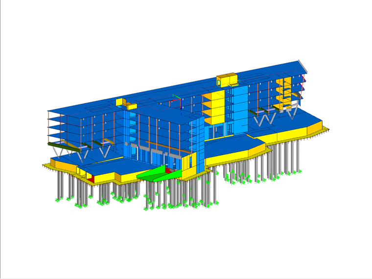
The Funke Media office includes an elongated double structure with a connecting bridge tunnel as well as a circular media tower with a supplementary steel structure and media facade. The buildings, with 6 to 7 aboveground stories, are designed as framed structures consisting of reinforced concrete flat slabs, columns, and shear walls in the access zones.
The unique architectural design elements are the V-shaped columns on the double structure ground floor. The SB3 quality V-shaped columns give the impression of a "floating" monolithic structure on this open story. For this design, the V-shaped columns intersect the building’s orthogonal support beams, which required massive steel components. Additionally, the columns’ reinforcement, their connections, and reaching concrete design strength class C50/60 were extremely complex challenges. To tackle this issue, the building company created a preliminary design of the V-shaped columns to determine potential issues (formwork, reinforcement installation, concrete compaction, and so on) and create a design plan for optimal results.
A shallow subway structure (tunnel and emergency exit) located under the building posed another technical challenge. A combined pile-slab foundation (KPP) was needed to meet the allowable soil pressure and more importantly, to minimize building settlement. To limit settlement, the bored piles with a diameter of 120 cm (47 in) along the subway structure (soil covering only 1 m [3 ft] from the lower edge of the floor slab) were extended to a rigid soil layer depth to serve as a "rigid abutment". Regular (nightly) survey control work in the subway tunnel monitored settlement calculations. To prevent vibration, measures were taken close to the emergency exit.
The foundation, as well as the complexity of the supporting structure, were particular challenges in both the planning and design phases. This required advanced engineering knowledge to minimize construction time and costs.
| Location | Friedrichstrasse 34-38 45128 Essen |
| Investor | KK Berliner Platz 1 Entwicklungsgesellschaft mbH & Co. KG Rüttenscheider Straße 62 45130 Essen, Germany |
| General Contractors - Joint Venture | AllesWirdGut Architektur ZT GmbH, Vienna, Austria www.awg.at FCP - Fritsch, Chiari & Partner ZT GmbH (Structural Engineering, Project Management, Vibration Analysis) www.fcp.at |


