KF Aerospace Centre for Excellence Spiral Staircase, Canada
Customer Project
A unique and extraordinary spiral staircase has been constructed in the KF Aerospace Centre for Excellence in Kelowna, BC, Canada. The staircase utilizes a special application of timber concrete composite (TCC) and includes a spiral clear span of 70 ft and a height of 23 ft.
Owner | KF Aerospace |
Architect | Meiklejohn Architects |
General Contractor | Sawchuk Developments |
Structural Analysis and Construction |
StructureCraft www.structurecraft.com |
Stair and Substructure Model Data
Model
Dlubal customer StructureCraft was responsible for the structural design and construction of this project. RFEM was used for the structural analysis.
Structure
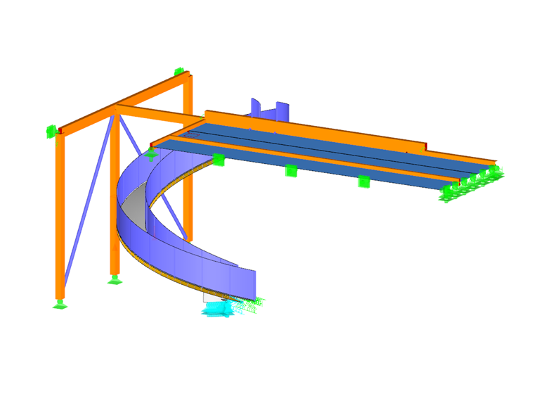
For KF Aerospace, StructureCraft’s engineers were presented with a unique and challenging design concept: connect two levels of the museum with a free-standing spiral CLT staircase. The spiral shape requires bending and twisting of the cross-laminated timber elements, which creates both bending about the strong and weak axes and torsional forces. This not only added complexity to the manufacturing process but also susceptibility to dynamic excitation, which typically governs the design of stair structures.
Using a special application of timber concrete composite (TCC), the spiral staircase was designed using double-curved cross-laminated timber with a concrete topping. The concrete provides the additional required mass to control vibrations over the staircase 70 ft clear span. Additionally, the composite action between the concrete and the cross-laminated timber significantly increases the overall stiffness. Support columns were therefore not required maintaining a highly aesthetic structure.
Design in RFEM
RFEM was used to determine the internal forces of the TCC system. Features like the diagrammatic input of spring stiffnesses and the adjustability of certain material properties for selected load cases helped to estimate the long-term behavior and creep deformation of the TCC system. The add on RF-Laminate helped furthermore to determine the bending and shear stresses in each layer of the customized CLT buildup.
Project Location
5800 Lapointe Drive, Kelowna International Airport (YLW)Keywords
Staircase Spiral staircase Cross-laminated timber CLT Timber Concrete Timber concrete composite
Write Comment...
Write Comment...
Contact Us
Do you have any further questions or need advice? Contact us via phone, email, chat or forum or find suggested solutions and useful tips on our FAQ page, available 24/7.

New
Timber Member Compression Perpendicular to the Grain acc. to NDS 2018 and CSA O86:19
A standard scenario in timber member construction is the ability to connect smaller members by means of bearing on a larger girder member. Additionally, member end conditions may include a similar situation where the beam is bearing on a support type. In either scenario, the beam must be designed to consider the bearing capacity perpendicular to the grain according to the NDS 2018 (Sect. 3.10.2) and the CSA O86:19 (Clause 6.5.6 and 7.5.9). In the new generation RFEM 6 and Timber Design add-on, the added feature 'design supports' now allows users to comply with the NDS and CSA bearing perpendicular to the grain design checks.
-
Why the eHORA map of Austria gives different snow loads than your Geo-Zone tool?
- Why does the load wizard "Member Load from Area Load" give unnecessary concentrated loads?
- How can I carry out case-related design for different load situations?
- How can I modify the lamella thickness for a glulam section in RFEM 6?
- How do I define a member as a cantilever and not as supported at both ends for serviceability or deflection design?
-
I would like to export nodal support forces of several load cases, load combinations and result combinations into an Excel spreadsheet in RFEM 6. How should I proceed?
- Where can find the option to hide the defined types (for example, design supports or effective lengths)?
- How do I create a user-defined Design Situation with my own chosen load combinations?
- How can I neglect torsion in the steel and timber design?
- How do I perform stability analysis to determine the critical load factor in RFEM 6?
- Why does the load wizard "Member Load from Area Load" give unnecessary concentrated loads?